Annual service of the gas furnace
This service sheet is a guide to maintaining a gas furnace for long life and no unnecessary failures. pilot furnace service click here 80 and 90% efficient furnace see below:
1. Set the thermostat well above the space temperature.
2. Check filter condition.
The furnace should be given a visual check first. The filter should be checked. Listen for abnormal noises or vibration. Smell for gas. Check for rollout of the burner flame. Do all components come on in sequence? The video below covers a brief overview of furnace condition.
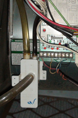
The IFC
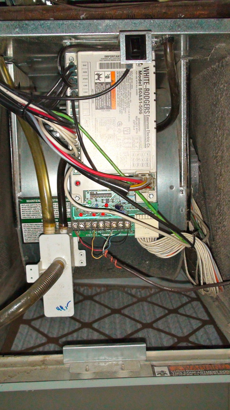
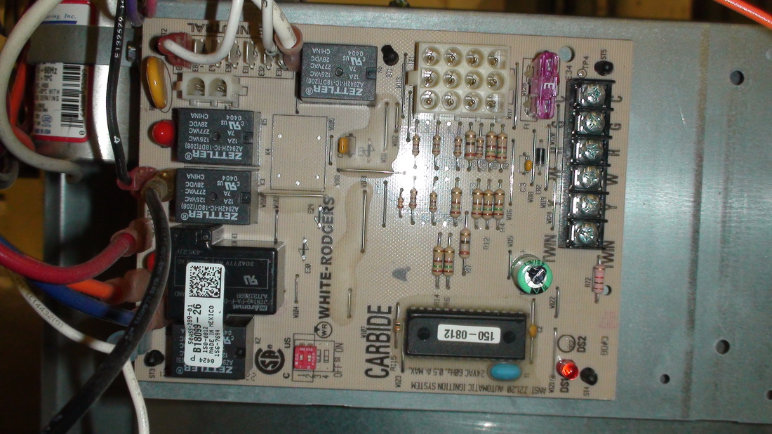
Most furnaces built after 1990 use an integrated furnace control (sometimes called an IFC, brain board or circuit board) to control all operation of the furnace. The sequence of operation of the furnace including inducer, flame safety control, failure diagnosis and circulating fan control are all controlled by this device. Below are 2 examples of IFCs. They are usually located in the blower compartment.
During the service, you will be checking the error codes when you test the components (HSI, flame rod, limit, pressure switch, flame safety shutdown). The error codes should be listed in the furnace. If you cannot find them,click here for some common error codes for specific furnaces. The error codes are your method of checking the IFC operation. IFCs do fail, however, all sensors should be checked for proper operation before replacing the IFC.
During the service, you will be checking the error codes when you test the components (HSI, flame rod, limit, pressure switch, flame safety shutdown). The error codes should be listed in the furnace. If you cannot find them,click here for some common error codes for specific furnaces. The error codes are your method of checking the IFC operation. IFCs do fail, however, all sensors should be checked for proper operation before replacing the IFC.
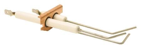
Check the hot surface ignitor
Check the HSI, silicon carbide type for hot spots. (are there any bright spots on the ignitor?) They indicate a failing ignitor. These ignitors are very delicate and if dropped they certainly will break.
Check the silicon carbide HSI ohms. Above 150 ohms, replace. Note: the 150 ohms number is not the number used by all manufacturers. They vary from150 ohms maximum to 250 ohms. If the ignitor has just been shut off, the reading will be less until it reaches room temperature. Requires use of ohmmeter.
Check the silicon carbide HSI ohms. Above 150 ohms, replace. Note: the 150 ohms number is not the number used by all manufacturers. They vary from150 ohms maximum to 250 ohms. If the ignitor has just been shut off, the reading will be less until it reaches room temperature. Requires use of ohmmeter.
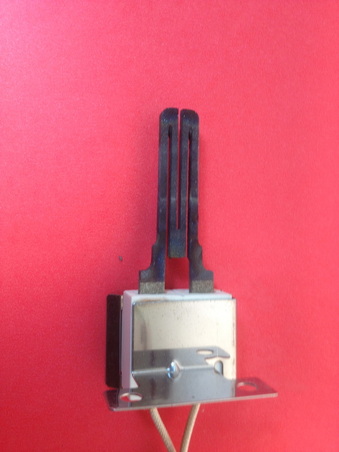
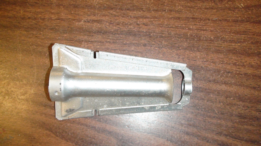
The above HSI is a silicon carbide unit. used but good.
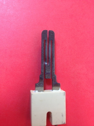
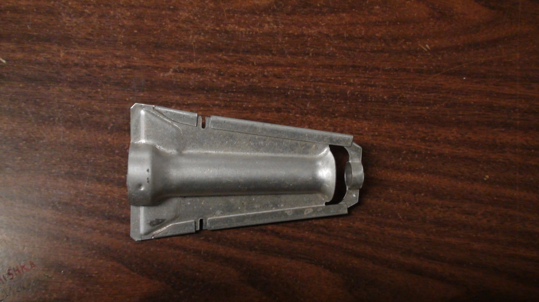
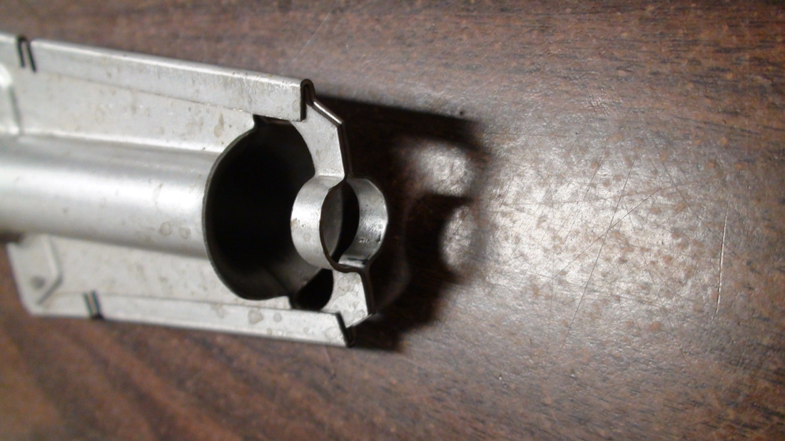
The above HSI is broken. The white spot shows the break.
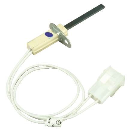
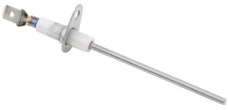
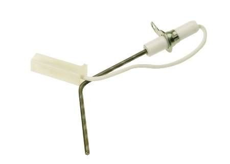
The ignitors above and below are called silicon nitride ignitors. They are much tougher and cannot be diagnosed as failed without an ohmmeter. The ohm reading on these ignitors should be 11-18 ohms.
Check flame rod microamps. This requires use of a micro ammeter. This meter is specialized and if you do not have one, simply remove, inspect and clean the flame rod.

The video below shows how to checkout and service the flame rod. You are also testing the flame safety control of the IFC to see if it works properly.
Clean the burners. use a toothbrush and a vac.

The following video covers cleaning burners, blower service and checking the heat exchanger.
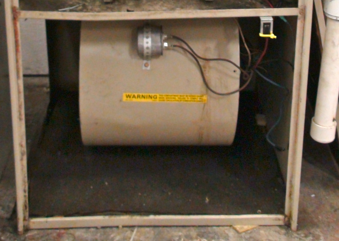
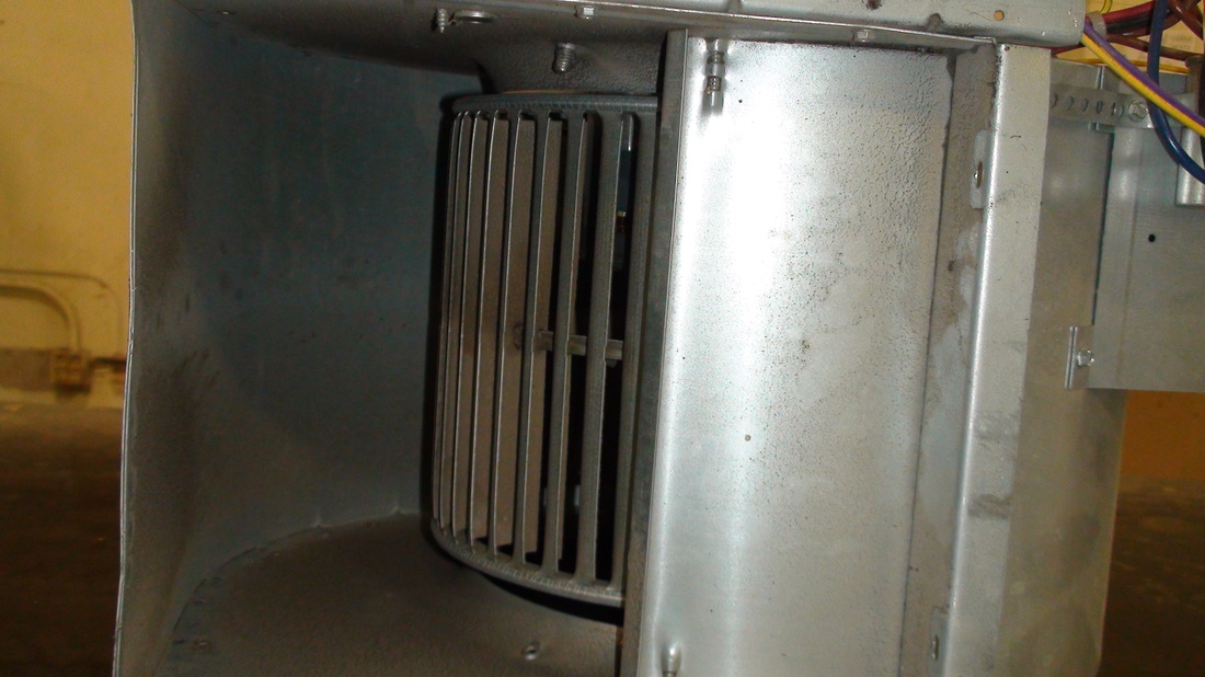
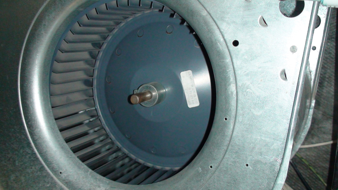
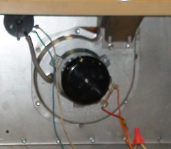
Check and clean blower assembly. The below blower is direct drive meaning the blower moves at the same speed as the motor. The blower wheel needs to be removed and cleaned separately from the motor. It should be cleaned with detergent. The motor must be kept dry. This involves completely disassembling the blower assembly. Also, on newer furnaces, the IFC is mounted on the blower assembly. It is not as tough as it may seem to remove the IFC. Just remove the mounting screws and lift it up and hold it up with wire or whatever.
Check blower motor bearings. This involves checking for looseness of the shaft and stiffness and resistance.
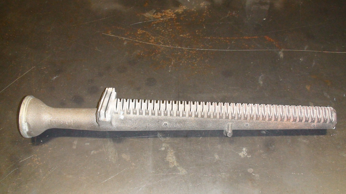
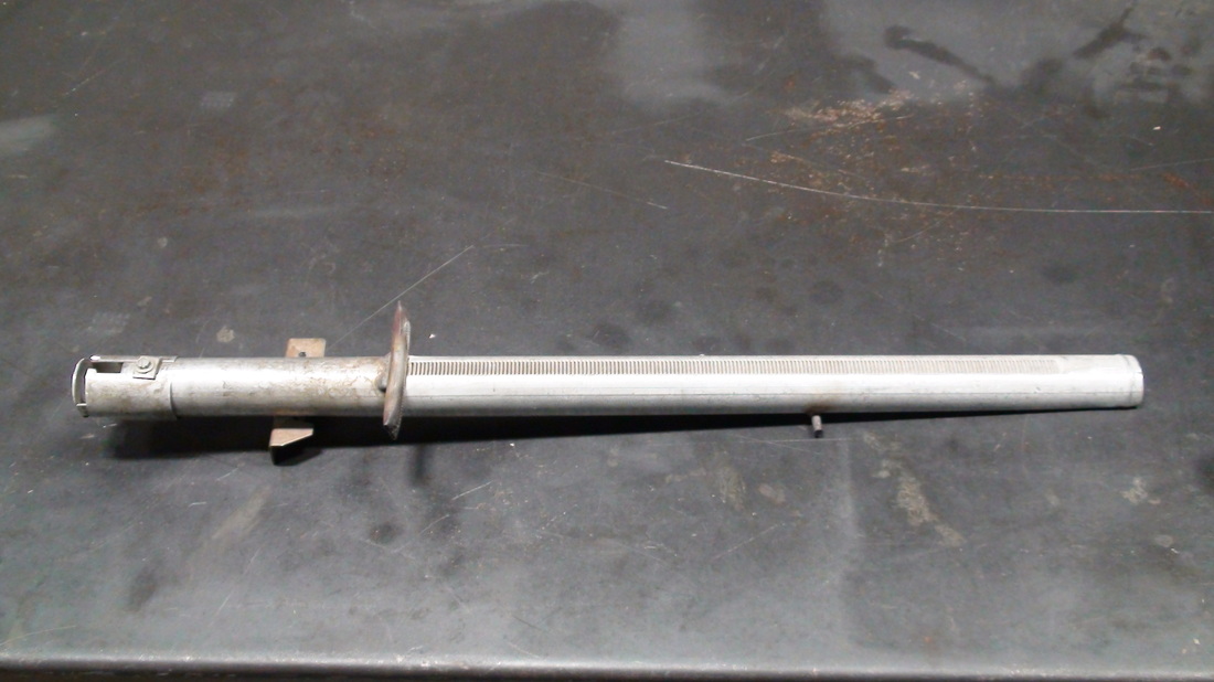
Check the heat exchanger
This could require removal of basic components. Click here to see what they look like. If you do not feel confident about this, it may be a job for a professional. I am not saying that you cannot check a heat exchanger yourself, but there is a lot of variation in design and construction. They can and do introduce CO into the house under certain conditions. A CO detector would be a good bet. I never argue with a man that wants to install a CO detector in his house.
Fire off furnace, adjust the burners and check for flame change when circulating fan starts. With the blower door in place, closely watch the the burners. When the blower starts, there should be no change in the flame. Occasionally when the blower starts, dirt will get into the burners and make orange sparkles. This is not flame change. A change in the burner flame means that the circulating air is mixing with burned gasses. This is what causes CO in the circulating air.
Fire off furnace, adjust the burners and check for flame change when circulating fan starts. With the blower door in place, closely watch the the burners. When the blower starts, there should be no change in the flame. Occasionally when the blower starts, dirt will get into the burners and make orange sparkles. This is not flame change. A change in the burner flame means that the circulating air is mixing with burned gasses. This is what causes CO in the circulating air.
The belt drive blower
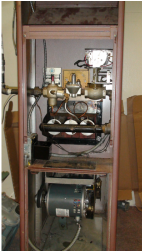
This gas furnace has a belt drive blower. The belt drive blower has been in use for many years. The belt transfers power from the motor to the blower wheel. The drive pulley is on the motor (below). During a service the belt should be removed and checked for cracks. While the belt is off, check the shaft bearings. Most of these blowers have oilers for lubrication and these should be oiled each season. The belt should be tensioned lightly. Belt tension of these belts is not the same as auto belts. Over tensioning will result in blower bearing failure.
Drive pulley
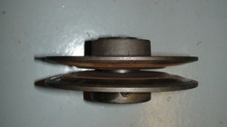
This pulley can has one side that can be adjusted by screwing the side in or out. As it moves out, it decreases the effective size of the pulley. This reduces the speed of the driven pulley and thus the amount of air circulating through the furnace.
If your blower is a belt drive, the motor pulley may be worn. Worn pulleys may squeal while running or wear out the belt early. If you replace the pulley, the belt must also be replaced. The following video will show you how to check the pulley for excess wear.
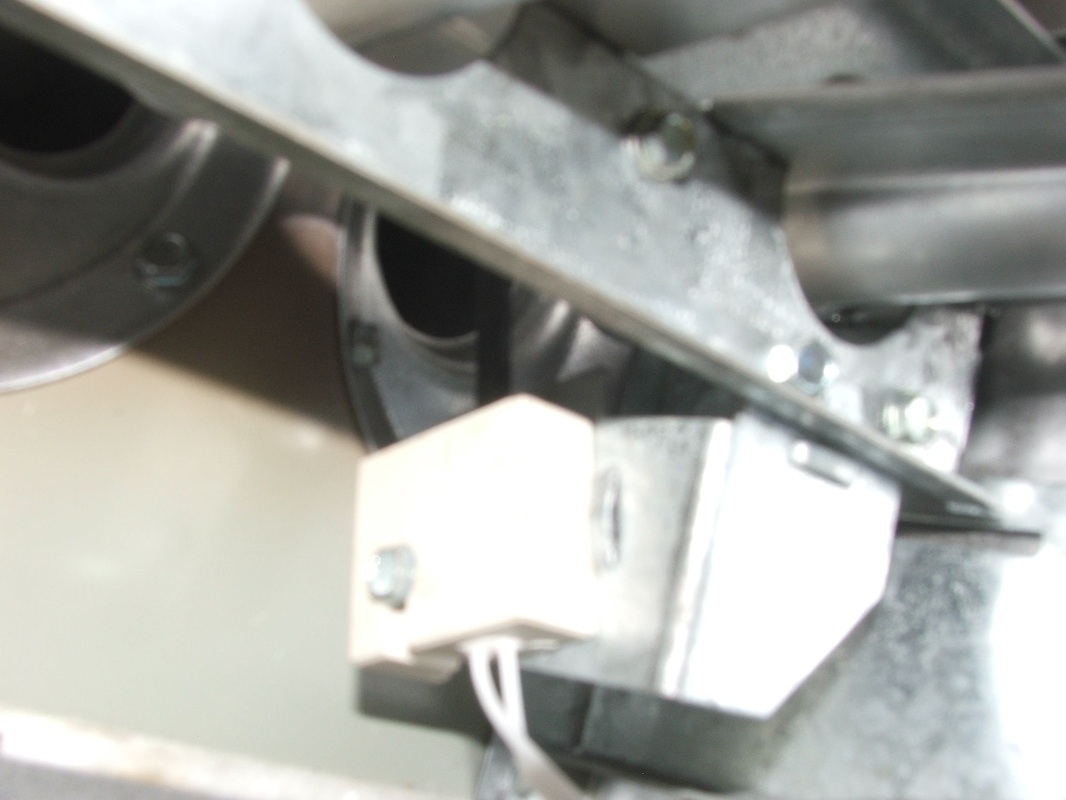
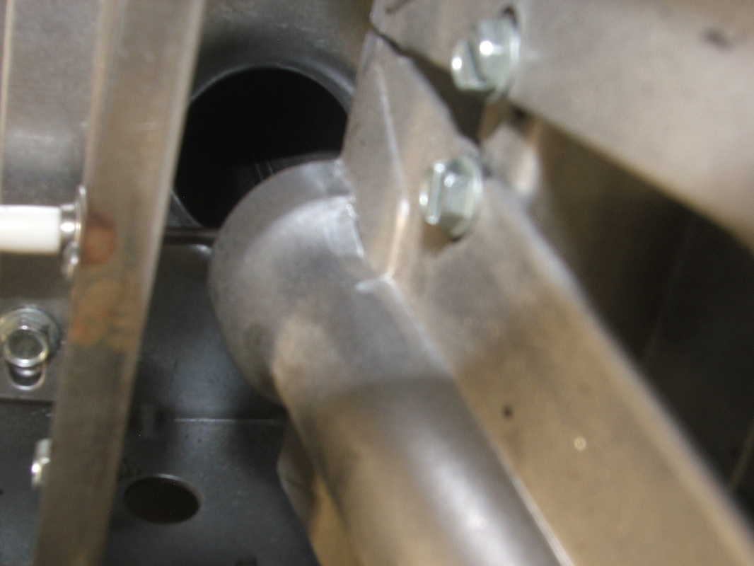
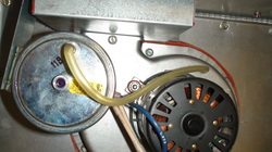
Check inducer
The inducer bearings need to be checked. Rotate the blower. It should move easily. Look for oilers. When it runs it should not vibrate.
The video below covers service of the inducer assembly and pressure switch.
pressure switch
While the burners are on, remove the tubing from the pressure switch. The burners should stop.
Check the limit.
The high temperature limit should be checked. What this means is that the fan should be disconnected and the furnace be fired off. This tests whether the burners will shut down if there is a fan failure.
If it has a belt drive blower, remove the belt. If it is direct drive blower, it is a little more complicated. If there is a white wire going to the motor, with the power off remove the wire and insulate it from contacting the chassis of the furnace. Then fire off the furnace. It should run normally but the fan will not come on. After 2-5 minutes, the burners should shut down. If the burners do not shut down after 7-10 minutes the limit has failed or is not wired correctly. Do not leave the furnace operating with a limit problem.
The video below covers how to check the limit switch.
Check amp draw.
The amp draw of all motors as well as the voltage should be checked and if possible, compare to rated amp draw on the motors. This video covers how to check amp draw and voltage tests for the inducer and fan motor.
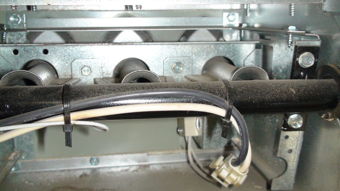
Check the gas pressure
The gas pressure in the manifold should be checked. This pressure determines the gas input to the furnace and if it is incorrect, the heat exchanger could be burned up or condensation may rust the heat exchanger.
The video below describes how to test gas pressure.
The video below describes how to test gas pressure.
The gas cock
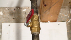
With the furnace off and the gas cock off, (note the gas cock on the left is off because the handle is across the flow of gas. Install the manometer on the outlet of the gas valve. Start the furnace with the gas cock on and check the gas pressure and compare it to the model plate. If the gas regulator cannot be adjusted high enough, you may need to check the gas input to the valve. Most gas valves have pressure taps on both ends of the gas valve.
The video below describes how to test gas pressure.
The gas valve in the video below is called the "Gemini" valve. The instructions in the video tell how to check pressure in this part.
Condensate drain
If the furnace is 90+% efficient, there is a condensate drain. The trap is located on the left. The lower tubing should be removed and a vac hose used to suck out the trap. This clears any trash out of the trap.
When the trap is clear, the trap should refilled with water.
Return to gas furnace design
When the trap is clear, the trap should refilled with water.
Return to gas furnace design
| servicing_gas_furnace.pdf |
