Oil Furnace Design
|
|
These furnaces use oil fired high pressure burners.
They use #2 fuel oil similar to diesel
The oil is pressurized to 100+ pounds and fed into a nozzle that atomizes the fuel which is ignited by a high voltage spark.
Oil furnaces work in a different way than gaseous fuels. In order to burn the fuel it must be atomized in a very hot environment so the fuel can evaporate to be burned.
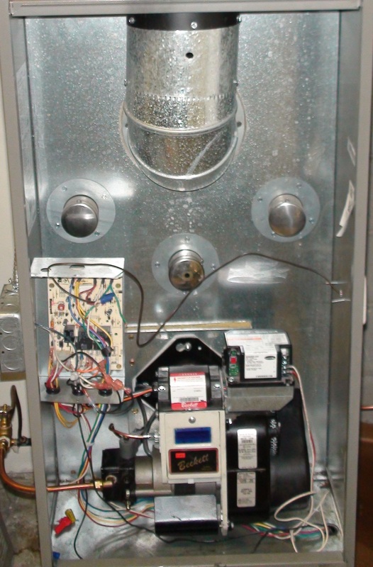
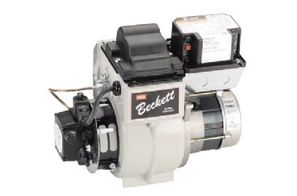
The gun oil burner
The pump is on the left. Center top is spark transformer to light the atomized oil. The cad cell relay is on top right. It is the flame safety control. Below the relay is the drive motor. On the far left is the fan and limit control.
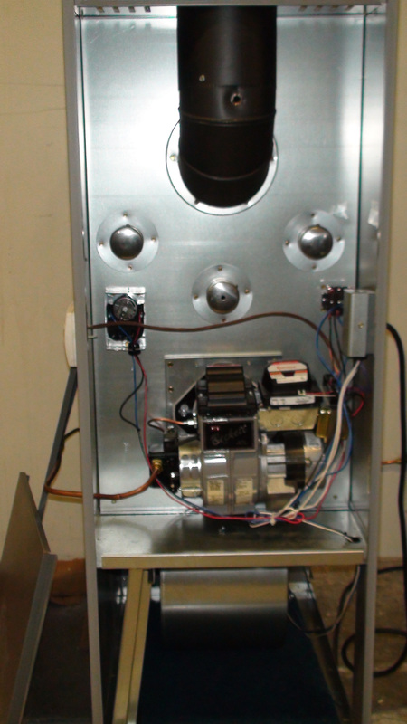
Oil furnace lowboy
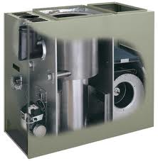
Older oil furnaces were long and low in height with the fan located behind the burner. Most oil furnaces are now what is called the high boy.
|
The furnace to the left is a highboy.It is much more compact with the blower underneath the combustion chamber.
|
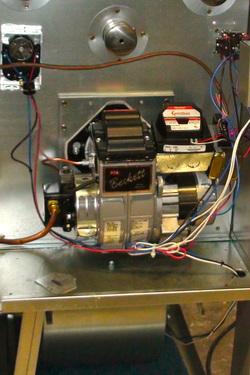
Oil Gun Burner
This is a modern gun pressure burner.
The oil pump is on the left. The drive motor is on the right.
The drive motor rotates the pump and powers a fan to supply air for combustion.
The oil pump is on the left. The drive motor is on the right.
The drive motor rotates the pump and powers a fan to supply air for combustion.
This end of the burner extends into the combustion chamber
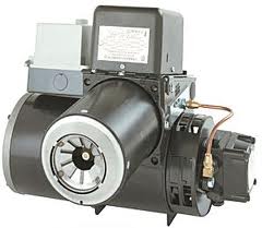
The flame comes out of the tube after being sprayed into tiny droplets by the nozzle, center of burner tube, and mixed with combustion air.
The square part on the top of the burner is the transformer.
The transformer provides an electric spark of between 8 and 20,000 volts to ignite the burner.
The square part on the top of the burner is the transformer.
The transformer provides an electric spark of between 8 and 20,000 volts to ignite the burner.
The nozzle
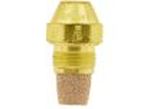
The nozzle is located in the center of the burner head.
It breaks the oil into tiny droplets so it can be evaporated by the heat of the fire and burned. For a further look at the nozzle, check here
It breaks the oil into tiny droplets so it can be evaporated by the heat of the fire and burned. For a further look at the nozzle, check here
The combustion chamber
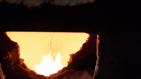
The flame burns inside a combustion chamber made of a ceramic fiber.
This material warms very quickly and glows orange. When it is hot, it reflects heat back into the flame to help evaporate the oil droplets.
This material warms very quickly and glows orange. When it is hot, it reflects heat back into the flame to help evaporate the oil droplets.
The video below shows a burner flame in the open without a combustion chamber. You can see the smoky droplets. These should be burned completely if the burner was installed inside a combustion chamber.
The burner flame
Below is a video on the burner flame. This shows the flame in a modern combustion chamber made of a ceramic fiber substance that heats up rapidly to reflect heat back into the flame to help evaporate the oil droplets. This also shows the effect of too much combustion air on the flame.
The burner flame efficiency is very dependent on the amount of air supplied. The common thought would be that not enough air would cause the most inefficiency of the burner flame.
However, the worst condition is too much air. Oil is a liquid and must be changed to a gas before it can burn. To change the oil to a gas, it must be heated. The heat required is supplied by other parts of the oil that has already burned and the combustion chamber reflecting heat from burned oil back into the remaining oil.
If there is too much combustion air, the cold air reduces the temperature of the flame and separates the droplets from each other. The results are incomplete gassification, lower heat exchanger temperatures and unburned oil going out the flue.
The video below shows the effect of too much combustion air.
When setting the air adjustment on the oil burner, you start with a smoky flame. The smoky flame actually releases most of the heat contained in the oil. A small amount of CO is produced because of incomplete combustion. Also some unburned oil is converted to soot. This the worst problem with this type of burn is the soot. Soot attaches itself to the cooler sides of the heat exchanger and creates an insulating blanket. This insulating blanket inhibits the transfer of heat from the burned oil to the air passing over the heat exchanger. You want to just eliminate the smoke and not add too much air.
The video below shows the small amount of air needed to get a good burn.
The video below shows the small amount of air needed to get a good burn.
The burner head.
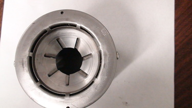
Early high pressure oil burners had what was called the sunflower flame. The flame was characterized by its propagation of flame 2-4 inches from the head of the burner.
The burner head on the left is called a flame retention head. The design of the slots serves to limit the amount of air supplied for combustion and to swirl the combustion air.
This tends to draw the flame very close to the head, thus its name: flame retention head. The temperature of this fire is several hundred degrees hotter than earlier burners. Burn efficiency is around 20% higher than the earlier burners. This type of burner is used almost universally in the industry.
In general, the hotter the burn, the more efficient the burn.
Once the combustion is complete the hot gasses enter the heat exchanger where the heat is transferred to the moving air from the fan.
The gun assembly
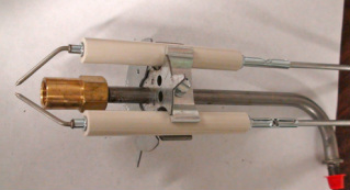
The gun assembly on the left transfers the high pressure oil to the nozzle which would be mounted on the brass fitting on the left.
The ceramic tubes hold the electrodes and conduct the high voltage current to the spark gap on the left.
The ceramic tubes hold the electrodes and conduct the high voltage current to the spark gap on the left.
The oil pump

the pump on left is an example of an oil pump. These pumps are capable of 100 -150# psi. The drive shaft is on the opposite side. There is a pressure regulator on the right side behind the 1/4" pipe plug. A bleeder is mounted on the lower right. The part on the top is a delay solenoid that keeps the oil supply to the nozzle off until the pressure reaches operating pressure.
This particular pump will pump 4 gallons oil per hour.
This particular pump will pump 4 gallons oil per hour.
Product specs for Webster pumps Click here
.
The ignition transformer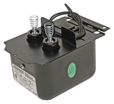 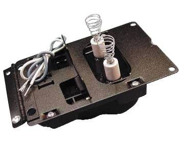 |
These transformers are capable of producing 10-20,000 volts to supply a spark to light the oil spray. The springs contact the electrodes to transfer power to the spark gap.
|
Below is a video showing the parts of an oil burner
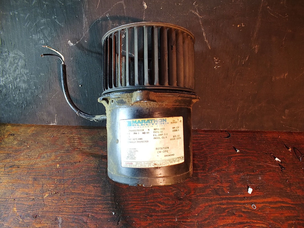
The pump motor
|
|
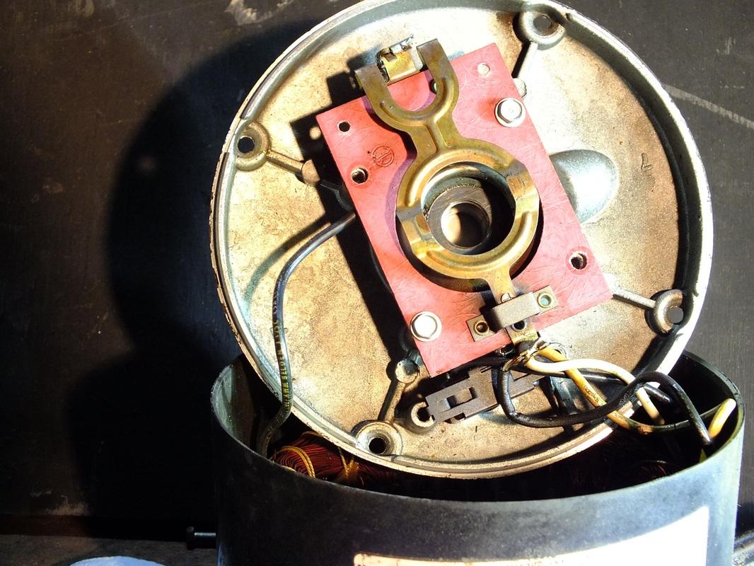
On the opposite end of the burner from the pump is the burner motor. This motor rotates the pump and powers the combustion air fan by direct drive.
The video below looks at the insides of this motor.
The video below looks at the insides of this motor.
Sequence of operation.
On a call for heat, the cad cell relay checks the cad cell to see if it is shorted. If it is above 20,000 ohms, the cad cell relay begins an ignition sequence.
First the power is passed from the cad cell relay to the drive motor on the burner assembly and ignition transformer.
The motor starts, driving the pump and the combustion blower.
As the pump pressure increases, the oil is sprayed into the combustion chamber.
At the same time, the ignition transformer establishes a spark across the electrode spark gap.
The oil is ignited and the light from the flame reaches the cad cell.
If the cad cell senses the light from the flame within the time safety period, (40 seconds or less) the burner stays on.
As the heat exchanger heats up, The fan switch closes and starts the circulating fan.
If at any time, the light from the flame is not sensed by the cad cell, the cad cell relay shuts off the burner and it must be manually reset.
