Electric Motors for HVAC
|
|
Back to graycoolingman
Terminology
Electric motors have some specific names for the parts that make up the motor.
The rotor is the rotating part of the motor that drives whatever load the motor is connected to.
The stator is the stationary electromagnet that reacts with the rotor and holds the motor frame.
The start winding is the the wiring that creates a magnetic field to start the motor.
The run winding is the wiring that creates the run magnetic field.
The brushes transfer electric power to the armature of the motor.
The armature is the rotating part of the brush motor.
The commutator is the contact bars on the armature that transfer power from the brushes.
The capacitor is an electronic rechargeable battery used in some motors.
In HVAC equipment we use mostly fan motors, compressor motors and pump motors.
The brush motor is usually small and commonly used in portable power tools and fans. The advantage to this motor is high starting torque and large power for small size.
Disadvantages are brushes that wear out and make sparks that could cause a fire, and lower efficiency operation.
This motor will operate on DC or AC power. This video shows how it works.
Disadvantages are brushes that wear out and make sparks that could cause a fire, and lower efficiency operation.
This motor will operate on DC or AC power. This video shows how it works.
The shaded pole motor is mostly used for small fan loads.
This type of motor is the simplest of the induction motors. Induction means there is no electrical connection between the rotor and the stator as there is in the brush motor. This makes the induction motor more trouble free and longer lived. This motor uses an offset winding consisting of 2 copper bars that produce and inductive magnetic field. These bars are the effective starting system for these motors. They have low starting torque, so are used for small applications with light fan blades.
These motors are very dependable but are somewhat less efficient than split phase motors.
The split phase motor
The split phase motor is an induction motor and covers a number of single phase motors.
The permanent split capacitor, capacitor start induction run, centrifugal start and capacitor start capacitor run are all split phase motors.
Below is a video giving a general overview of the permanent split capacitor fan motor.
The permanent split capacitor, capacitor start induction run, centrifugal start and capacitor start capacitor run are all split phase motors.
Below is a video giving a general overview of the permanent split capacitor fan motor.
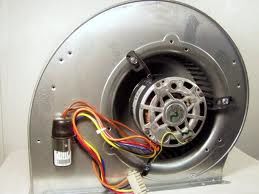
Fan motors generally are low starting torque motors. They sometimes use a run capacitor to assist in starting and increase the efficiency of the motor operation. The following video demonstrates the starting characteristics of the PSC motor using different sizes of capacitors.
The PSC motor can be either single speed or multispeed.
If it is multispeed, it has multiple taps on the run winding. The shorter the winding, the faster the speed. The color code of the wiring for most motors is White for common, Black for high speed, yellow for medium high, blue for medium low, and red for low speed. The video below explains how these motors are wired.
If it is multispeed, it has multiple taps on the run winding. The shorter the winding, the faster the speed. The color code of the wiring for most motors is White for common, Black for high speed, yellow for medium high, blue for medium low, and red for low speed. The video below explains how these motors are wired.
When an electric motor runs, it also generates electric power. The power generated runs opposite of the incoming power. This power is called back EMF. As the motor speed increases, the back EMF increases. This controls the speed of the motor by reducing the amperage draw. This video explains it.
PSC motors use run capacitors to start and increase efficiency of the operation. Capacitor strength can be tested with a capacitor tester or there is a calculation that can be used to test the capacitor while under load. The video below demonstrates how this calculation is done.
When the capacitor fails open, the PSC motor sometimes will not start but sometimes will start. It depends on brand and design. In either case, the motor will run inefficiently and may overheat. The video below demonstrates how this works. This video will be available on 2-2-15.
more coming
