Annual Service of the Oil Furnace
|
|
Oil furnaces use a flammable fuel. leaks left can cause fires. Things like puffback are usually not devastating explosions but can cause a fire or extensive property damage. There are also lethal voltages involved. Know your limits.
Set thermostat above space temperature
Check /change air filter
Once the unit is checked for excessive soot in combustion chamber, open damper (below) to check smoke pipe. If the smoke pipe and combustion chamber have heavy soot inside, do not service the unit. The furnace must be cleaned prior to service. If the smoke pipe is sooted then the heat exchanger is also sooted. Servicing an oil furnace that is sooted is a waste of time.
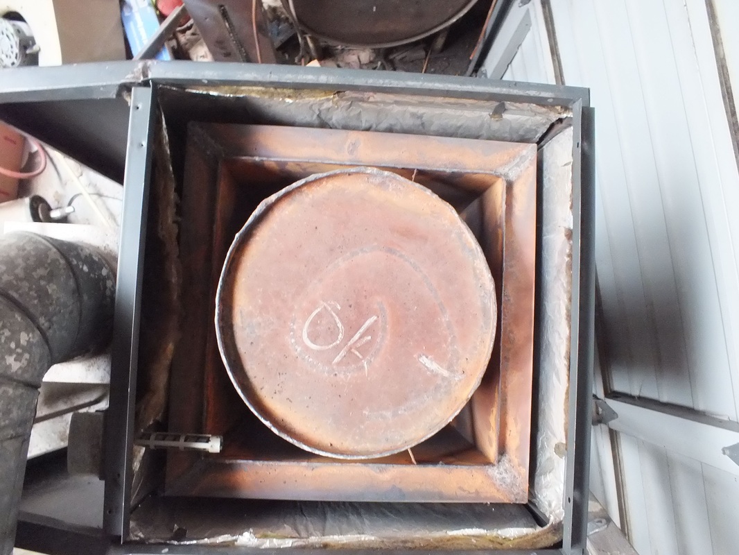
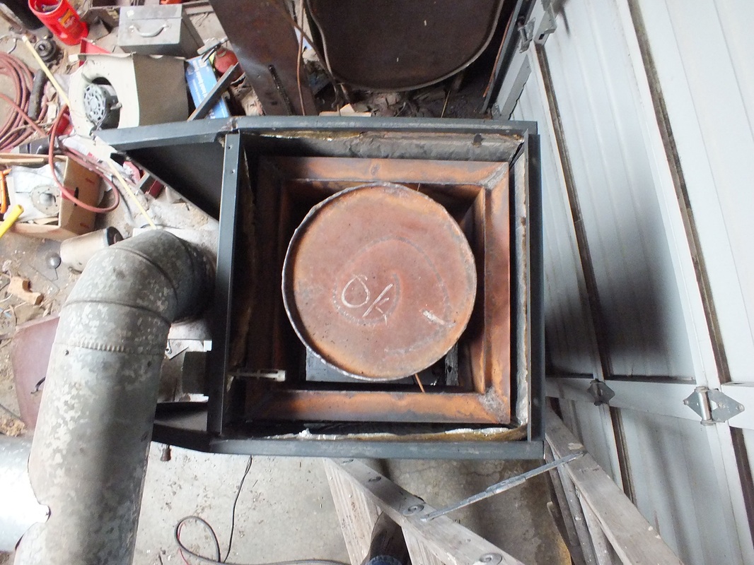
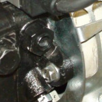
The furnace heat exchanger
Below is a furnace heat exchanger. The combustion chamber is the center barrel. The surrounding square section is the heat exchanger. Oil furnace heat exchangers are subject to soot buildup. Soot is deposited on the sides of the heat exchanger and insulates the heat exchanger causing less heat transfer. One burner manufacturer states that the insulating value of 1/8" of soot is equal to 1" of fiberglass insulation. Soot is not normal for oil furnaces. It builds up when the burner is adjusted incorrectly or the nozzle is not spraying properly. If the burner is operating efficiently, the heat exchanger does not need to be cleaned annually. However, a 5 year schedule should be considered unless the is a burner problem. The furnace below is 40 years old and has never been cleaned. There was quite a buildup heavy metals (looks like sand) in the heat exchanger. The videos below demonstrate the cleaning of the heat exchanger.
|
|
Many furnaces have clean outs that facilitate the cleaning of the heat exchanger. This video shows a typical set of clean outs.
This video demonstrates the method used to vacuum out the heat exchanger. The shop vac used is not recommended as it not powerful enough to do a complete cleaning job, but it demonstrates where to access the heat exchanger and the use of compressed air to break loose soot.
If the heat exchanger has no clean outs, The cleaning must be done from the vent pipe fitting and the combustion chamber. When using the compressed air near the combustion chamber, you must be careful not to damage the combustion chamber. The video below covers cleaning without clean outs.
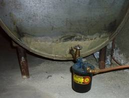
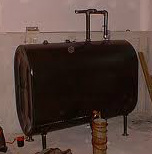
Turn off unit. Find the oil filter. If the oil tank is in the basement, it should be next to the tank. If it is a 2 pipe system, the valve is probably near the filter canister.
The oil shut off valve
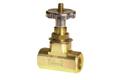
This valve is placed between the oil tank and the filter. The valve handle pulls up the shaft in the middle to open the valve. It is made of a low temperature solder that melts and closes the valve with spring pressure when there is a fire. When closed, the handle should be loose.
|
|
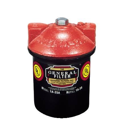
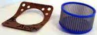
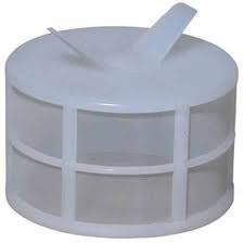
The oil filter canister
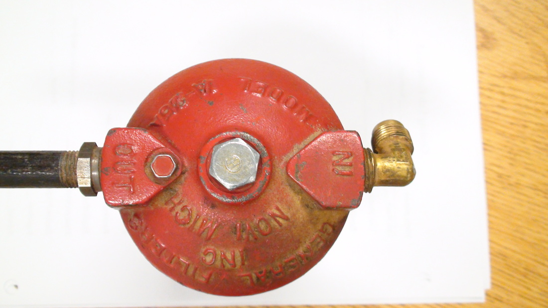
These are oil filter canister views. This seems to the standard for oil filtration. The bottom of the canister is removed by loosening the center bolt on top. Remember to shut off the oil valve just ahead of the canister. When the oil valve is shut off the valve handle should be loose on the shaft. Tap it lightly to make sure it seals off. Remember, the entire oil tank contents are behind the valve and you could have an incredible mess. Loosen the bolt with a coffee can under the canister. Place generous amounts of newspaper around the coffee can. When the bolt is loose, tap it with a wrench or small hammer to break it loose from the gasket. When you do this, a little oil will spray out from the canister. The newspaper should catch it. With the canister off open the oil valve a small amount and flush some oil out into the coffee can.
The oil filter element
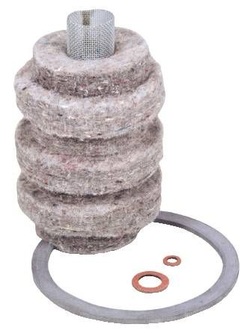
This or something similar to it should be inside. If it has not been replaced for several years, it is probably plugged. The canister should be cleaned with strong detergent and hot water. Cleanliness is very important in all this work. Replace all gaskets with new ones from the filter element kit. When the filter is replaced, the canister should be bled. The small screw at the outlet side should be loosened with the valve open and bled until oil comes out. Wipe down the entire canister with a rag. Replace the newspaper with a clean one. The filter should be checked later for oil drips. This filter should be replaced every heating season.
Although this still seems to be the standard for the industry, this thing is from the dark ages. There are throw away spin on filters that are far superior.
The following is a video of the filter change:
Although this still seems to be the standard for the industry, this thing is from the dark ages. There are throw away spin on filters that are far superior.
The following is a video of the filter change:
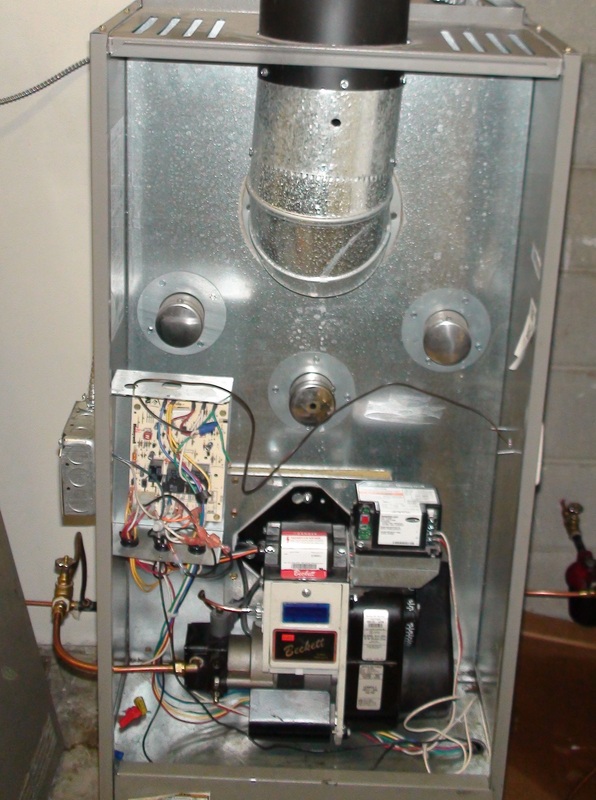
The oil burner gun assembly
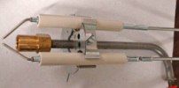
The gun assembly moves the oil under pressure to the nozzle and provides the spark to light the oil.
The electrodes (the cylindrical white parts)provide and insulated path for the high voltage to reach the spark gap. The nozzle is mounted on the end of the gun (brass part). The burner service continues below:
The electrodes (the cylindrical white parts)provide and insulated path for the high voltage to reach the spark gap. The nozzle is mounted on the end of the gun (brass part). The burner service continues below:
Replacing the oil nozzle
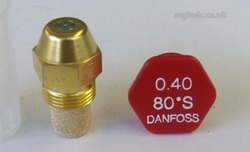
Nozzles are the most important part of the oil burner. They use 100+# of pressure to spray a fine mist of fuel oil into the combustion chamber.
It is absolutely of the highest importance that it be kept clean. The filter on the end of the nozzle should not be touched. Use the container the nozzle came in to place it in the nozzle adaptor. When replacing the nozzle replace like for like. The above nozzle is .4 gallons per hour. The spray angle is 80 degrees. The spray type is "S". For nozzle information click here
It is absolutely of the highest importance that it be kept clean. The filter on the end of the nozzle should not be touched. Use the container the nozzle came in to place it in the nozzle adaptor. When replacing the nozzle replace like for like. The above nozzle is .4 gallons per hour. The spray angle is 80 degrees. The spray type is "S". For nozzle information click here
Cleaning the gun assembly
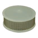
Pump screen
Many pumps have inlet screens. They are placed inside the cover of the oil pump. If the burner has not been serviced for several years, the screen may be plugged. While they can be cleaned, if a new one is available, its a better repair. Remember when you remove the pump cover the oil should be shut off at the tank if the burner is below the tank level. Also if available, the gasket should be changed. Silicone can be used in a pinch. Below is a video of a pump with its cover removed and the screen shown:
Below is a gun burner disassembly showing the parts
Below is the reassembly and setup of the oil burner
Pump pressure
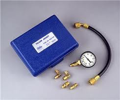
The burner pump runs at a minimum of 100#. Some new burners run at up to 150#. The pressure regulator seldom changes its calibration however, its a good idea to check the pressure with a service.
This test requires a pressure gauge like the one on the left. The gauge is mounted at the outlet of the gun line.
When installed the pressure should go up to the set pressure and stay there until it is shut off. After the motor is shut off, the pressure should drop 20% of the set pressure and stay. If it drops lower after a few seconds, the regulator is failing.
Pump pressure adjust.
On the pic to the right, the pressure adjust is the slot screw in the center of the hex nut. Turn clockwise to increase pump pressure.
This is a demonstration of how to test oil pump pressure.
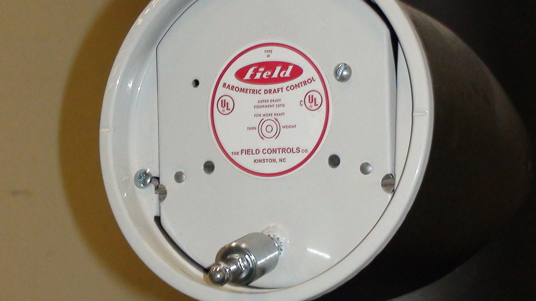
Setting the draft.
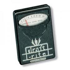
Once the burner has been reinstalled it should be fired off and the draft set. On left is a draft gauge.
The draft should always be negative, that is when operating air should be drawn into the furnace.
Once the furnace is running for 10 minutes, the draft can be checked. The overfire draft should be approximately -.02 in wc
The smoke pipe draft should be -.03-04.
To adjust draft, the weights on the draft regulator (above) can be moved in or out. The more the weights are set to close the regulator, the stronger the draft.
Draft should not be increased above the -04 number as this will draw the exhaust gasses through the furnace too quickly which will reduce the heat exchange and cause higher fuel usage.
If these numbers cannot be achieved, there is a problem with soot. See troubleshoot.
If you do not have access to a draft gauge, you can set the draft until it does not puff out exhaust gasses upon startup.
Setting the flame

This is a closeup of the combustion air inlet of the gun burner. The slots on the diameter of the cylinder are called mass air dampers. This adjustment should not be opened for nozzles of less than 2 gallons per hour.
The adjustment that is linked to the tang on the upper left near the gun line should be used for most adjustments.
With the unit running and stable, this adjustment should be moved until you have a smoky fire.
The adjustment that is linked to the tang on the upper left near the gun line should be used for most adjustments.
With the unit running and stable, this adjustment should be moved until you have a smoky fire.
A view through the inspection door.
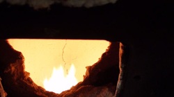
This view shows the flame inside the combustion chamber. When adjusting combustion air, the flame should be adjusted to where the tips of the flame are slightly smoky.
At this point, there are 2 ways to proceed.
If you have a combustion analyzer and smoke pump go here If you do not have these tools, continue down the page.
At this point, there are 2 ways to proceed.
If you have a combustion analyzer and smoke pump go here If you do not have these tools, continue down the page.
Setting the flame without an analyzer
If combustion analysis tools are not available, set draft by holding something like a lit cigarette near the sampling hole. It should pull into the hole.
Set smoke by setting the combustion air to smoky tips. Then adjust until the flame appears bright yellow. This is not the best and most efficient procedure but will do in a pinch. Back to oil furnace design
Set smoke by setting the combustion air to smoky tips. Then adjust until the flame appears bright yellow. This is not the best and most efficient procedure but will do in a pinch. Back to oil furnace design
