Troubleshooting the capacitor
|
|
Capacitors are electrical devices that can discharge and shock or electrocute. Any electrical device should be powered down before removing and replacing parts.
Capacitors can fail in 3 ways.
They can short out. An ohmmeter or capacitor tester will read 0 ohms.
They can fail open. An ohmmeter or tester will read OL.
They can read lower than 10% of the rated strength.
Capacitors are fairly easy to troubleshoot if you have the tools.
The capacitor is essentially a battery that charges very quickly.
In earlier years, we would use an ohmmeter to determine if the capacitor is operating. The problem with this type of testing is that it does not show if the capacitor strength within specifications.
Generally, when testing a capacitor with this method, you would use the
R X 10,000 scale. When connecting the probes to the capacitor terminals, the battery in the meter charges the capacitor and creates an increasing stored voltage which makes the needle move toward very low resistance to flow to more resistance as the capacitor charges.
The video below demonstrates this method.
The video below is an overview of troubleshooting of the capacitor
Most modern multimeters used for HVAC have a capacitor test mode.
When the capacitor is to be tested, it must be removed from the circuit and tested without any connection to the circuit. The video below shows how the test is done. Usually, 10% above and 10% below rated strength indicates a good cap.
When the capacitor is to be tested, it must be removed from the circuit and tested without any connection to the circuit. The video below shows how the test is done. Usually, 10% above and 10% below rated strength indicates a good cap.
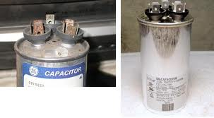
Many units use dual capacitors that are simply 2 separate capacitors in the same can.
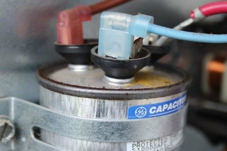
There is a common terminal (labeled com) that both capacitors are connected to that is wired to incoming power. The other 2 terminals are (herm) for the compressor start terminal and (fan) for the outdoor fan start terminal.
The video below covers how to troubleshoot these capacitors.
There is a common terminal (labeled com) that both capacitors are connected to that is wired to incoming power. The other 2 terminals are (herm) for the compressor start terminal and (fan) for the outdoor fan start terminal.
The video below covers how to troubleshoot these capacitors.
When testing capacitors, we usually use a capacitor tester. However, there is a method testing capacitors under load.
This method uses a calculation to determine capacitor strength under load. The calculation is: amperage draw as measured by a clamp ammeter on the run lead multiplied by 2650, divided by the voltage read across the cap. This voltage is not supply voltage, but back EMF.
Below is a video that covers how to do this calculation.
