Gas furnace with pilot troubleshoot, no main burner
|
|
Now we assume the pilot is on but the gas burner will not come on. To go farther you will need a voltmeter and the ability to use it.
Most appliances operate their controls from a small transformer that supplies 24 volts that travels through the thermostat, through a high temperature limit to keep the appliance from running at too high a temperature, to energize the gas valve through the 2 terminals mounted on the black plastic on the top of the gas valve.
When the voltmeter leads are placed on the terminals of the gas valve, it should read 24 volts AC. If so continue
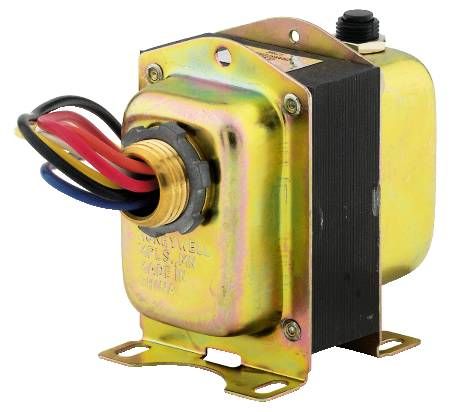
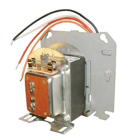
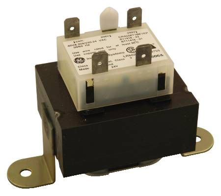
If the voltmeter reads 0 the problem is not in the gas valve. Next, the 24 volt transformer (below) should be checked. If there are terminals mounted (right and below left), place the probes on them with the power on and the thermostat calling for heat. If there are only wires coming out of it there will probably be wire nuts on the wires that can be loosened and the probes inserted. If there is voltage, the transformer is ok. Next If voltage is not available, go here
Most appliances operate their controls from a small transformer that supplies 24 volts that travels through the thermostat, through a high temperature limit to keep the appliance from running at too high a temperature, to energize the gas valve through the 2 terminals mounted on the black plastic on the top of the gas valve.
When the voltmeter leads are placed on the terminals of the gas valve, it should read 24 volts AC. If so continue
If the voltmeter reads 0 the problem is not in the gas valve. Next, the 24 volt transformer (below) should be checked. If there are terminals mounted (right and below left), place the probes on them with the power on and the thermostat calling for heat. If there are only wires coming out of it there will probably be wire nuts on the wires that can be loosened and the probes inserted. If there is voltage, the transformer is ok. Next If voltage is not available, go here