Gas valve replacement setup
If at any time you are unsure of your abilities in this project, stop! Call a professional.
The gas valve itself is not complicated to replace. If you have some plumbing skills, you can do it.
Turn off all power to unit. Remove wires from valve. (If there are only 2 wires on the valve, they are interchangeable. If there are more than 2 mark them or take a pic for replacement.)
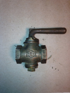
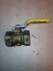
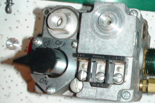
Turn off gas cock shown on the left and lower left.
Note, if your gas cock looks like the one on the left, replace it.
These valves are big leakers and no longer safe.
Turn off all power to unit. Remove wires from valve. (If there are only 2 wires on the valve, they are interchangeable. If there are more than 2 mark them or take a pic for replacement.)
Turn off gas cock shown on the left and lower left.
Note, if your gas cock looks like the one on the left, replace it.
These valves are big leakers and no longer safe.
.
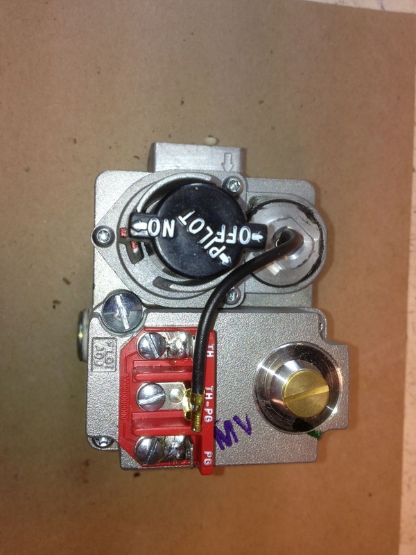
Remove existing combination gas valve and replace with new valve.
Note, the new valve may not look exactly the same, but should have the same terminals as the old one.
Use pipe dope on all tapered pipe fittings.
Note the arrows on the valve should point downstream of gas flow.
The pilot tube connection must be carefully installed or it will cross thread and sometimes is hard to make leak free.
The more complicated part of this procedure is the setup of the valve.
When the valve is installed and wired, the pilot should be lit. When lit and holding the pilot on, shut off the gas cock. The pilot will go out. Wait until you hear a "click" from the valve. If the environment is noisy, place your hand on the valve body and you should feel the click. The time period between the loss of pilot flame and the click should not be more than 3 minutes. Once the pilot safety clicks off, turn on the gas cock and attempt to light the pilot without pressing the red button or knob. It should not light. If it does, the valve is leaking by and should not be used.
If all is well, the firing rate can be set.
The unit should now be fired off. Make sure no other gas appliances are operating. The meter will have to be "clocked" to be sure it is running at the specified BTUH
rating.
Gas meter dials
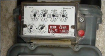
This will require viewing the dials of your gas meter. On the lower left there are 2 dials. One is marked 1/4 foot and one is marked one foot.
The one foot dial moves one cubic foot of gas per rotation. Natural gas is usually 1000 BTU per cu ft. (check with your supplier)
Time the rotation on the one foot dial for one revolution in seconds.
When watching the dial, do not start the time until the needle is on the upswing. This eliminates inaccurate readings from the dial sticking on the downswing.
As BTUs are rated per hour, and there are 3600 seconds in one hour, divide the number of seconds by 3600, then multiply by 1000 for the BTU input per hour.
Example: time for one rotation=27 seconds. (3600/27) X 1000=133,333 BTUs.
This is then compared to the gas input listed on the unit data plate. If there is only a 2 foot dial, divide by 1/2. Do not use the 1/4 foot dial.
To watch a video on clocking the gas meter, click below
This is a model plate on a gas appliance.
Note the gas input. 40,000 BTUH The output is not important for this operation.
If you look at the model # you will see TG9S040A08MP11A. The 040 stands for the gas input in thousands.
If you look at the model # you will see TG9S040A08MP11A. The 040 stands for the gas input in thousands.
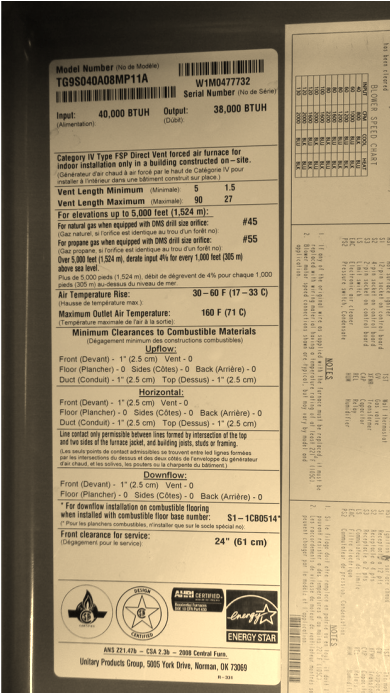
The number of BTUs you are looking for is input. This furnace is 40,000 BTUH.
If the clocking of the meter does not equal this number, the manifold pressure needs to be adjusted.
If the clocking of the meter does not equal this number, the manifold pressure needs to be adjusted.
Manifold pressure setting
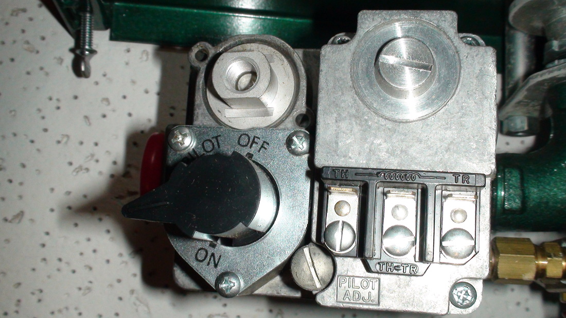
Start the furnace and make sure no other appliances are operating. The slot head screw on the upper right of this gas valve must be removed.
Adjusting the pressure
Here it is shown with the cap removed.
The adjustment screw is rotated clockwise to increase pressure.
After you adjust pressure, reinstall cap before clocking the meter again.
Continue until gas input is correct.
Back to troubleshoot
The video below covers adjustment of the manifold pressure.
The adjustment screw is rotated clockwise to increase pressure.
After you adjust pressure, reinstall cap before clocking the meter again.
Continue until gas input is correct.
Back to troubleshoot
The video below covers adjustment of the manifold pressure.
