Electrical diagrams for HVAC
|
|
Electric diagrams are there to assist you in troubleshooting. When troubleshooting, sometimes the equipment must be energized. The danger of electrocution is always there. Do not proceed if you are not confident in your abilities, call a professional.
Electric diagrams tell us more about a piece of equipment than anything else. There are 3 different types of diagrams:
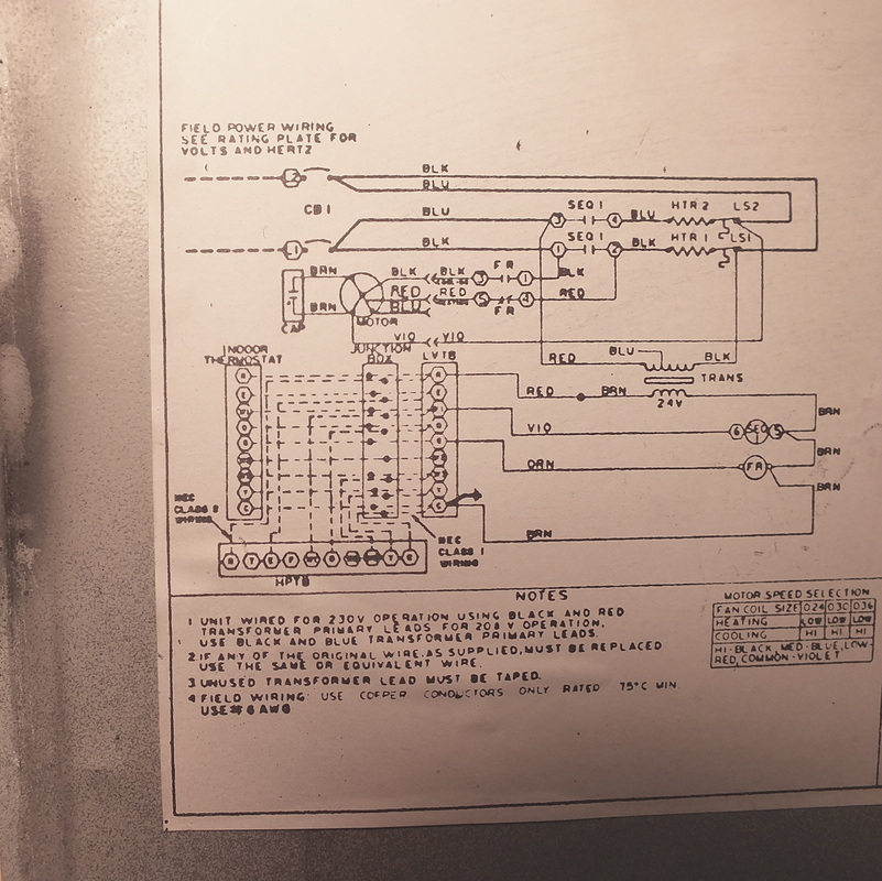
The first is the Elementary, ladder or schematic diagram. This one is an aide for sequencing a piece of equipment. Its layout looks somewhat like a ladder with power sources as vertical lines, with loads and switches in between. This layout places components in such a way that it makes it easy to follow the electricity as it passes through the circuit. This sometimes requires components that have 2 or more voltages passing through different parts of them be placed in different parts of the diagram.
An example of this would be a relay that has its solenoid coil energized by 24 volts, but the contacts of the relay control a voltage of 120 volts.
The low voltage coil will be placed in the low voltage circuit, but the contacts will be in the 120 volt circuit.
In order to identify a component split up this way, both parts of the component will be labeled in the diagram with the same designation.
The relay could be marked at the coil as R1, and the contacts will also be marked R1
We use this diagram to sequence or to tell how the equipment moves electricity through the system to make the unit operate.
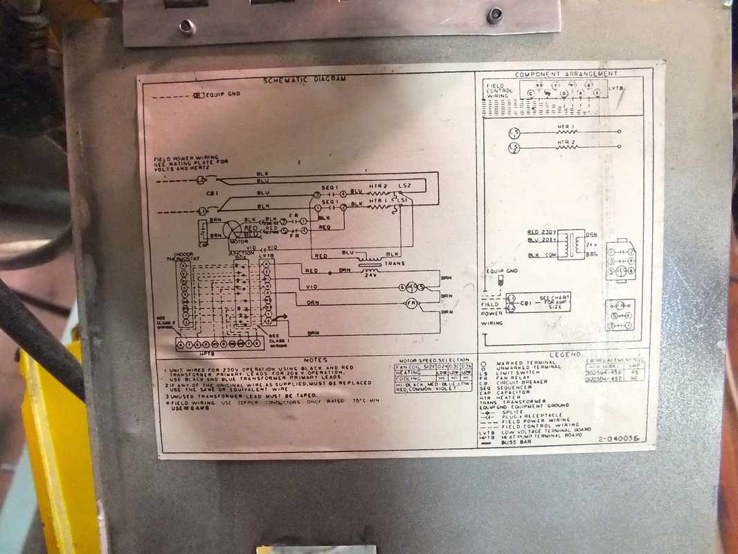
The wiring diagram shows where the wires are mounted to the components and usually including wire color codes and sometimes numbers for wire identification. The wiring diagram helps locate components and wires in the unit that you find in the schematic diagram.
The position diagram is a map that shows the position of all the components in the electrical panel. The position diagram is not included in all manufacturer diagrams.
The videos below are a training tool to help understand how to read the schematic diagram.
The first is the Elementary, ladder or schematic diagram. This one is an aide for sequencing a piece of equipment. Its layout looks somewhat like a ladder with power sources as vertical lines, with loads and switches in between. This layout places components in such a way that it makes it easy to follow the electricity as it passes through the circuit. This sometimes requires components that have 2 or more voltages passing through different parts of them be placed in different parts of the diagram.
An example of this would be a relay that has its solenoid coil energized by 24 volts, but the contacts of the relay control a voltage of 120 volts.
The low voltage coil will be placed in the low voltage circuit, but the contacts will be in the 120 volt circuit.
In order to identify a component split up this way, both parts of the component will be labeled in the diagram with the same designation.
The relay could be marked at the coil as R1, and the contacts will also be marked R1
We use this diagram to sequence or to tell how the equipment moves electricity through the system to make the unit operate.
The wiring diagram shows where the wires are mounted to the components and usually including wire color codes and sometimes numbers for wire identification. The wiring diagram helps locate components and wires in the unit that you find in the schematic diagram.
The position diagram is a map that shows the position of all the components in the electrical panel. The position diagram is not included in all manufacturer diagrams.
The videos below are a training tool to help understand how to read the schematic diagram.
Here we add a thermally actuated switch
We have added a normally closed high temperature limit to shut off the unit in case of overheat.
We have added a fan motor to move the heat throughout the structure and a thermally activated switch to turn on the fan when the heat exchanger warms.
Here we have added a low voltage control circuit.
This one adds a fan circuit with a manual switch and a coil in the low voltage and a set of relay contacts to start the fan.
In this one, we have added 2 speeds to the fan motor. One that runs the fan motor in low speed when the heat exchanger is warm, If the manual fan switch is closed, there is a single pole, double throw relay switch that disengages the low speed and energizes the high speed.
We have added here an integrated thermostat that brings all the controls into a single device such as a wall thermostat.
