Oil furnace controls
|
|
As on all types of furnaces, there are controls to insure that the furnace does not operate during unsafe conditions.
|
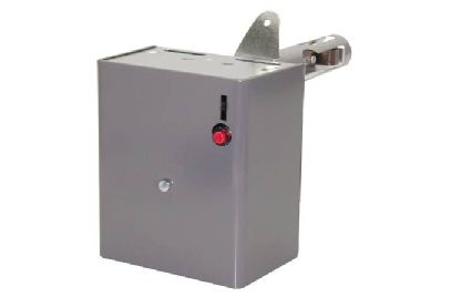
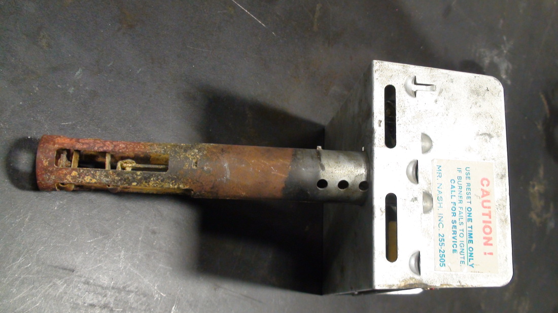
The stack switch relayThis control has a sensor that is placed inside the vent pipe to sense the temperature of the exhaust gasses. There is a bimetal at the end of the probe. When the unit is off, the bimetal leaves the "cold" position switch on.
When the thermostat calls for heat, the circuit is made for the control to supply power to the to the burner motor and the ignition transformer to supply spark to light the burner. |
|
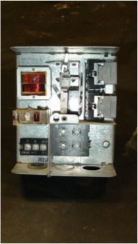
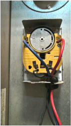
The control side of the stack switch.Thermostat terminals are located on the lower left.
The burner motor and transformer wires are hooked on the lower right side. When the thermostat calls for heat a heater starts. As the vent pipe heats, the bimetal warms and moves to close the "hot" position switch. When this switch closes, the heater is shut off. If the bimetal does not heat, the heater in the control does not shut off and after the trial for ignition time period is over, shuts off the burner. The time period for the trial for ignition is as long as 90 seconds for older units, and approximately 70 seconds for newer units. |
This control will only try for ignition once. If it fails to light, a manual reset must be pressed. These controls are designed this way to avoid excessive amounts of unburned oil to fill the combustion chamber. It is not recommended to reset the burner more than once without finding the source of the problem.
These controls are pretty much considered antiques and have not been installed on new furnaces for over thirty years.
These controls are pretty much considered antiques and have not been installed on new furnaces for over thirty years.
The following is a video of the operation of the stack switch
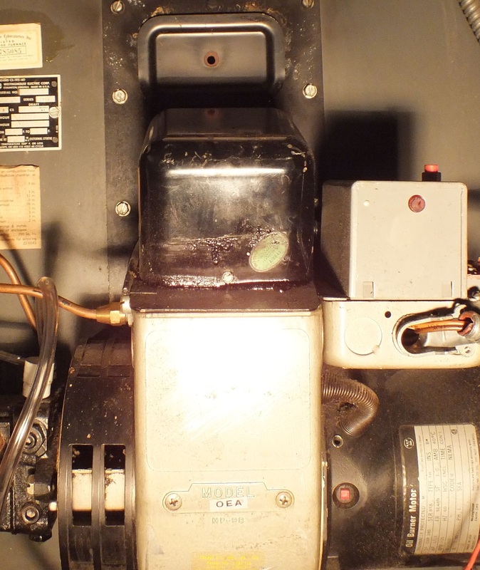
The cad cell primary

This primary has been the standard of the industry for over 35 years. It uses a light sensitive cell to determine if the burner has ignited. This control is mounted usually on the burner assembly. Upon a call for heat, this control turns on the burner motor and the spark transformer. When the burner lights, the light from the flame is sensed by the cad cell and the burner continues to run. If the cell does not sense light within the programmed time period, the control shuts off the burner and it must be reset by pushing the red button. The trial for ignition time is 45 seconds.
The cad cell
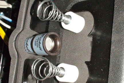
The cad cell is located in the middle of the 2 springs of this spark transformer. In operation, the cad cell is pointed toward the flame.
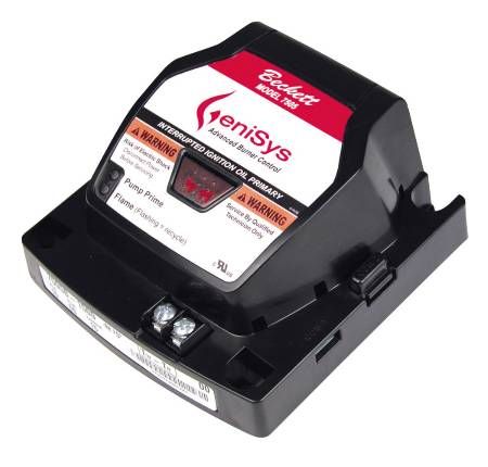
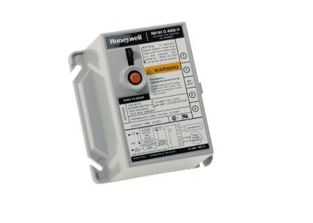
This is a newer type of cad cell primary
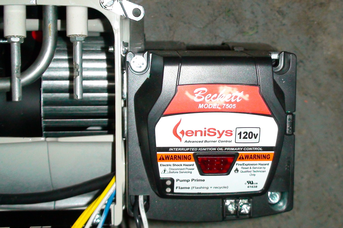
This control is a newer style of the cad cell relay. The time period for ignition can be adjusted and is usually set at about 30 seconds. This control has a safety feature to prevent continued reseting of the primary by the home owner. The unit will only allow 1 reset of the safety. To reset the control you must hold down the reset for 45 seconds.
The fan and limit switch
This control uses the heat from the heat exchanger to turn on the circulating fan when it warms and off when it cools.
The control also has a limit feature that shuts off the burner if the heat exchanger gets too hot.
The video below demonstrates how the fan and limit switch works.
The control also has a limit feature that shuts off the burner if the heat exchanger gets too hot.
The video below demonstrates how the fan and limit switch works.
