Gas furnace design and operation
|
|
|
The furnace assembly
The gas is supplied to a gas valve. If the flame safeties in the gas valve allow, the gas passes through the gas valve and is supplied to the burner by a manifold when there is more than one burner. for a more complete explanation of how a gas valve works, check here. A manifold supplies equal amounts of fuel gas each of the burners (below). The brass fittings on the manifold shown are called orifices or "spuds". The fittings limit the gas flow through them by their size. For a discussion of setting the proper gas flow to the burners, click here.
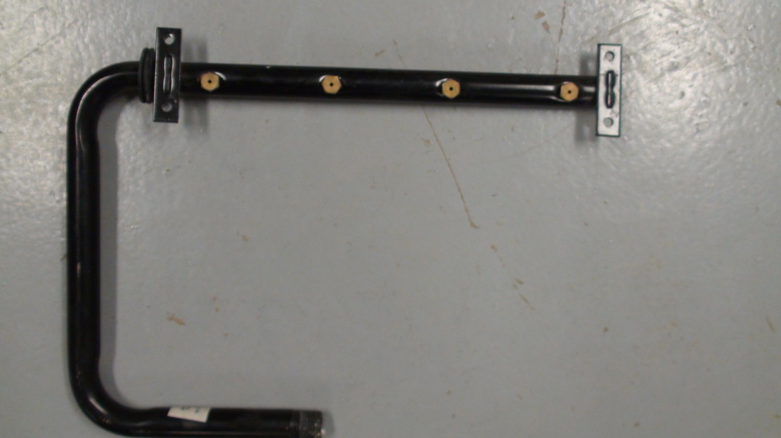
The burner
The burner is designed to supply primary air to the gas to prepare it to burn.
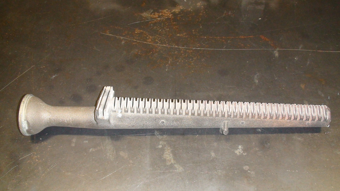
Look at the burner above. It is a older cast iron ribbon type burner. The gas comes in at the left and the shape of the burner indicates that there is a venturi at that end.
The venturi speeds up the air flow by reducing the size of the tube the gas passes through thus drawing primary air in to mix with the fuel gas. The fuel/primary air mix then passes out the slots in the top of the burner. As the mixture comes out the slots, it mixes with air surrounding the burner (secondary air) and is lit by the pilot.
This type of burner is usually used in natural draft furnaces.
These natural draft furnaces used the flame's temperature to move the burnt gasses through the furnace heat exchanger and out the metal vent. For a look at different types of heat exchangers click here.
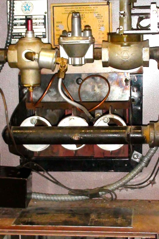
On these older natural draft furnaces, The primary air to the burner was adjustable. In the pic above, there are 3 burners. Each has a butterfly valve on the end. To adjust the air you loosen the screw and close the butterfly. The flame should turn yellow. Then slowly open the butterfly until the flame just turns blue. Do not add more air as that will cool the flame and reduce efficiency.
The above burner is also adjustable by moving the slide on the left.
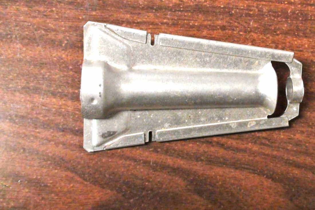
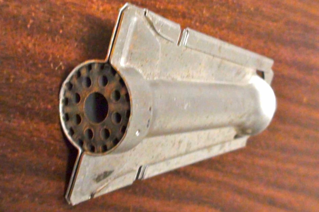
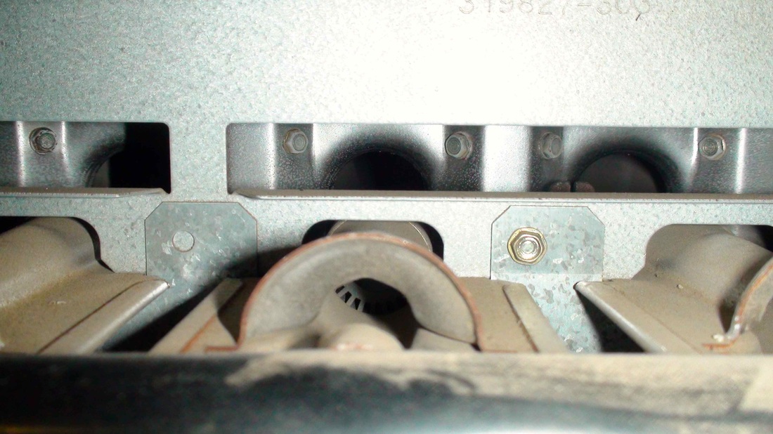
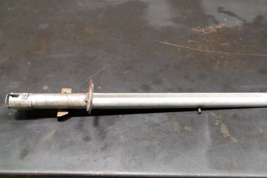
The above burners are called inshot burners. The pic on the left shows a view from the manifold. The flame moves horizontally into the heat exchanger tube. Most of these burners do not have primary air adjustments.
They can only be used on induced draft furnaces because the flame is horizontal. Virtually all high efficiency furnaces use this type of burner.
They can only be used on induced draft furnaces because the flame is horizontal. Virtually all high efficiency furnaces use this type of burner.

Early gas furnaces used a pilot to ignite the burner. The pilot (above) both ignited the fuel and provided a safety to shut down the gas supply if the pilot was not present. For a more detailed explanation of the thermocouple flame safety click here. Natural gas requires 1100 degrees F to ignite so all early furnaces used a gas flame from the pilot for ignition.
The video shows how the pilot works.
The video shows how the pilot works.
Furnaces built in the last 25 or so years have changed the way the gasses are removed and the pilot has been eliminated to increase fuel efficiency.
Small fans called "inducers" have been introduced to remove the gasses from the furnace.
Once the gas is burned, the heat released passes through a heat exchanger made of thin sheet metal. The heat conducts through the sheet metal and is picked up by air passing over the heat exchanger from a circulating fan and conducted through ductwork to the various rooms of the structure.
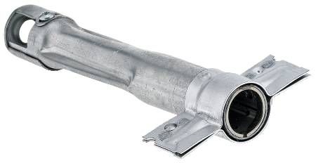
Inducer
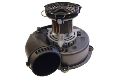
These fans pull burned gasses from the appliance.
Pilot burners have been eliminated in favor of spark ignitors and hot surface ignitors
Hot surface ignitor
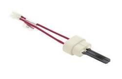
This is one type of hot surface ignitor. It heats up to 2300 degrees F and glows brightly and is placed near the burner tubes to ignite the fuel. This type of ignitor is very fragile and must be handled with care.
Silicon nitride ignitor
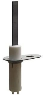
This one is tougher and appears to last longer, but also glows at high temperature.
Flame rod
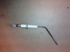
The flame rod is a sensor that tells the electronic controls that the flame is present.
When the furnace is turned on, the inducer comes on and can be heard when in front of the furnace. When it proves to the furnace that it is working, the hot surface ignitor comes on for a warmup time. After this time, gas is allowed to enter the burners. When they light, there is a proving circuit using a flame rod sensor to insure that the furnace has lit.
After 30 to 45 seconds, the circulating fan comes on and the cycle is complete.
If at any time the there is an interruption in the cycle the appliance will shut down.
After 30 to 45 seconds, the circulating fan comes on and the cycle is complete.
If at any time the there is an interruption in the cycle the appliance will shut down.
Newer furnaces are rated for efficiency
They are described as either
80% efficient or 90+% efficient furnaces. Click on the efficiency you are interested in for a more complete explanation of their operation. For an annual service sheet for these furnaces click here
80% efficient or 90+% efficient furnaces. Click on the efficiency you are interested in for a more complete explanation of their operation. For an annual service sheet for these furnaces click here
