Setting gas input
When troubleshooting, understand you are working with potentially lethal voltages and a highly flammable gas. If you do not have the ability to do these operations safely, do not attempt them.
  |
Checking natural gas inputGas input should be checked when the unit is installed, when the gas valve is replaced and many times when annual service is done.
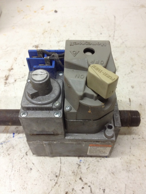
If the input is too low, condensation of burned gasses may occur in parts of the heat exchanger not designed for it. If input is too high, the heat exchanger can overheat and be damaged. Natural gas is supplied to structures from a high pressure gas line (service techs do not deal with gas pressures upstream of the meter). When the gas passes through the meter, its pressure is generally reduced to 7" water column. (We will discuss water column pressures further down the page). The normal pressure in the regulated line downstream of the meter can vary somewhat but should be no lower than 5 " wc. On many gas valves, any pressure above 14 " wc is damaging to the valve. The accompanying photos below are of various models of gas valve. |

Below is a discussion of the method of checking gas input by measuring the gas pressure at the burner.
For another method of checking gas input by clocking the meter, go to the bottom of the page.
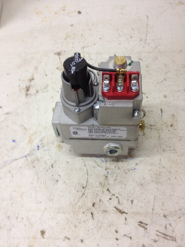
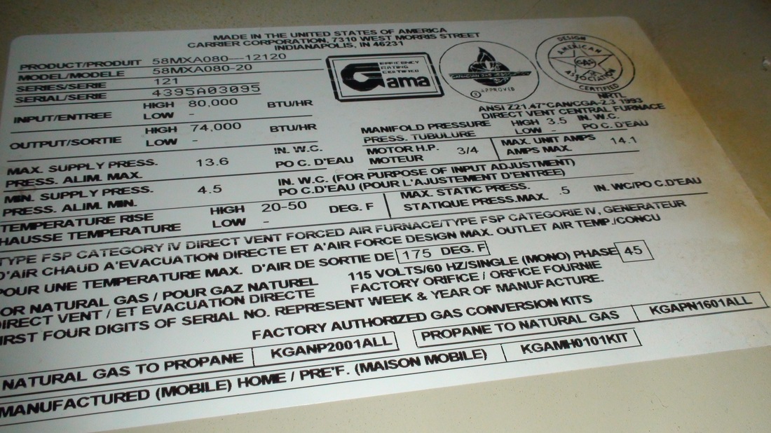
Once the gas reaches the gas valve, the pressure is reduced to what is called "manifold pressure". This means the pressure is regulated from approx 7" wc to a lower pressure that corresponds to the manifold pressure listed on the model plate. Note on the model plate below upper right, manifold pressure is listed as 3.5" wc. 3.5 "wc manifold pressure is a common manifold pressure for gas appliances, however the model plate should be checked every time.
The above pic shows the pressure regulator with its cap removed on the right.
When adjusting, the slot screw inside is turned clockwise to increase pressure.
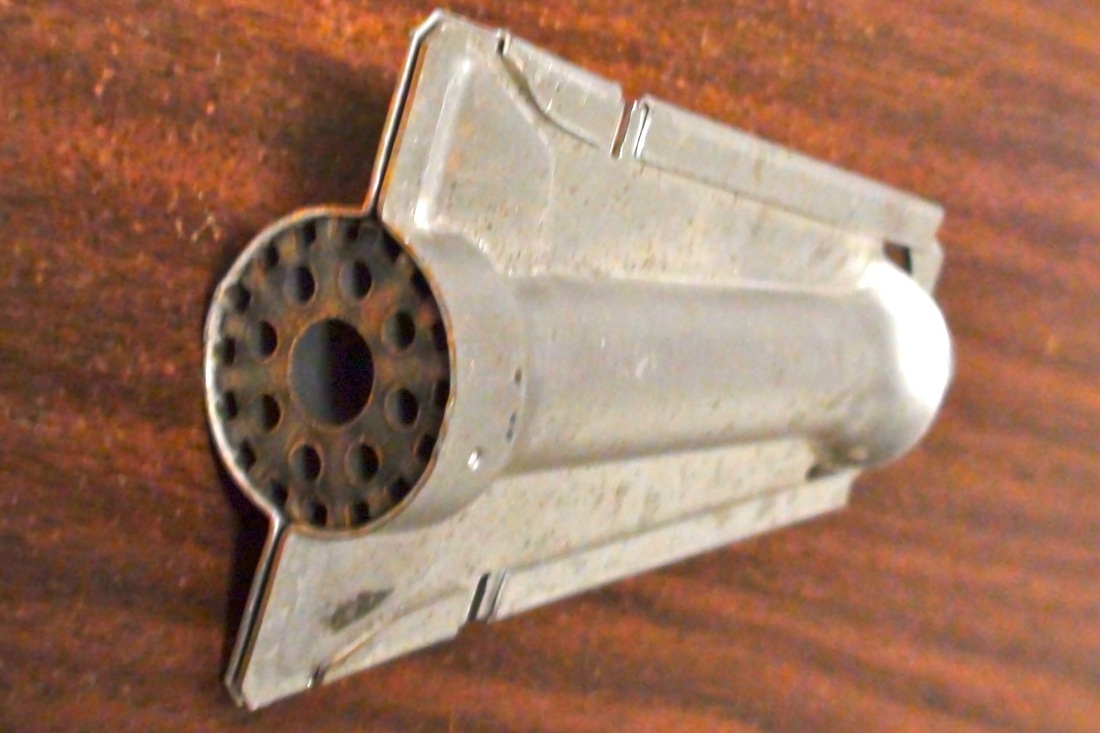
The gas then passes to the manifold (below) which distributes the gas to the various burners.
When adjusting, the slot screw inside is turned clockwise to increase pressure.
The gas then passes to the manifold (below) which distributes the gas to the various burners.

Click to set custom HTML
|
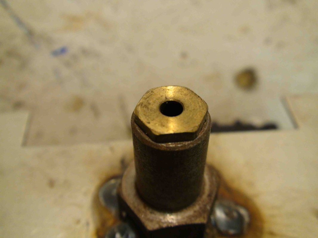
The brass orifices have a hole drilled to a specific size. An orifice shown on the left will usually be marked with the drill size of its hole.
To understand this you need to know how numbered drills are labeled. Numbered drills are are sized from #0 to #80. #0 is the largest and #80 is the smallest. Thus if the number stamped on the fitting is #45, that is the drill size of the hole. The size of the hole along with the manifold pressure determines the amount of gas that will flow into the burner. Click here for a chart of gas input for orifices at specific pressures. As an example, a #45 orifice with 3.5 in wc, will supply 17072 BTUs to the burner. |
Testing procedure
To do the test, you must have a pressure tap so you can install a manometer.
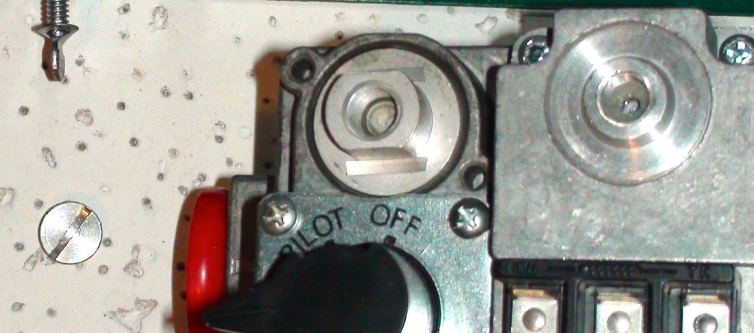
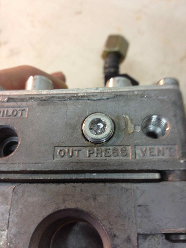
The gas valve on the left shows a allen head plug labeled "out press" for manifold pressure. The plug should be located near the outlet.
The furnace should be off, the gas cock should be off and the power should be shut off before removing the plug.
The manometer must be able to read a maximum of 10 in wc for natural gas and 15 in wc for propane.
Below is a video showing where the pressure taps are located on differing gas valves.
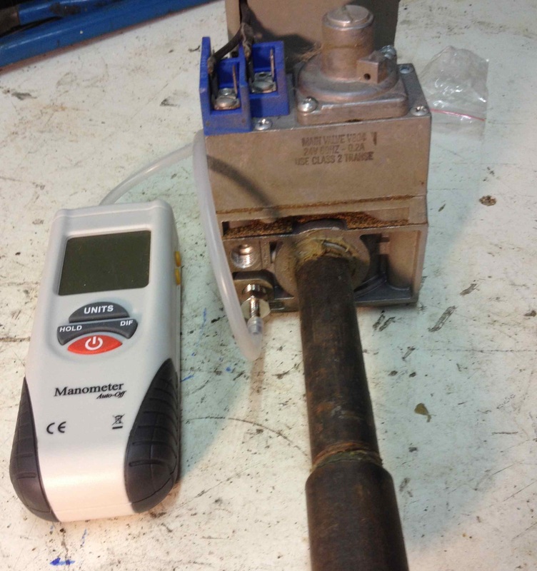
Below is the gas valve with the manometer attached.

Above are several types of manometers. Each are described below:
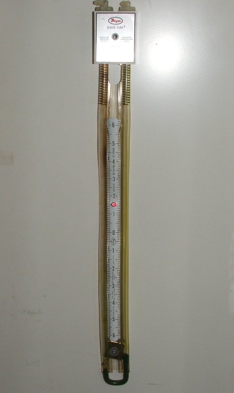
The u tube manometer
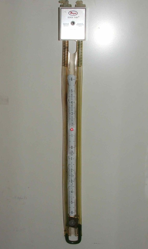
This is the simplest type of manometer. Water (or there is a red oil that wont freeze) is added into the tube until it levels out at 0. One end is left open and the other is connected to the tap being tested. The level will drop on one side and rise on the other and the total of the 2 levels is the pressure in in wc.
This tool is the basis for all these tools. It must be kept vertical.
This tool is the basis for all these tools. It must be kept vertical.
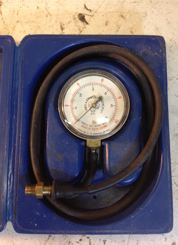
The "Ritchie gauge.

Ritchie is a brand name for a diaphram type analog gauge.
These gauges are fairly accurate but quite delicate and cannot be mishandled. They should be calibrated regularly. (calibration may cost more than the gauge).
These gauges are fairly accurate but quite delicate and cannot be mishandled. They should be calibrated regularly. (calibration may cost more than the gauge).
The Magnehelic
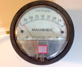
This also a brand name.
These gauges are accurate but are also quite delicate.
These gauges are accurate but are also quite delicate.
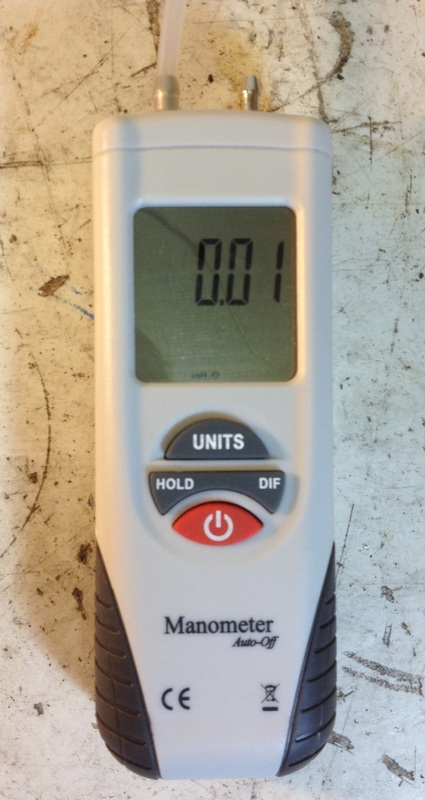
The electronic manometer

Electronic manometers have many uses because they can usually read from .01 inches wc to approximately 10#.
They supposedly recalibrate themselves without outside calibration.
They can read in all scales.
They supposedly recalibrate themselves without outside calibration.
They can read in all scales.
Below is a video comparing the types of water column gauges
Start the test
OK, now we have hooked up the manometer to the gas valve. With all piping secure and the manometer zeroed, fire off the furnace. When the burner lights, the meter should read according to the model plate. If it reads too low, the regulator screw should be turned clockwise to increase pressure.
When the adjustment is made, the cap over the regulator screw should be tightened and pressure rechecked. Having the cap off can sometimes give a false reading.
The following video covers how to adjust manifold pressure.
When the adjustment is made, the cap over the regulator screw should be tightened and pressure rechecked. Having the cap off can sometimes give a false reading.
The following video covers how to adjust manifold pressure.
Clocking the meter.
If a water column gauge is not available or as a double check of the gas input to an appliance, you can clock the meter.
Before beginning, shut off the gas cocks to all appliances on the gas line.
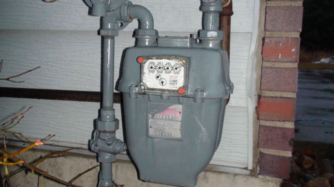
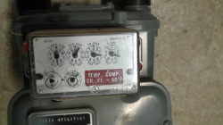
Start the appliance to be tested. At the meter, look at the dials. The meter on the left has 6 dials. Ignore the top 4. They are for billing only. The one on the left is the 1/4 cu ft. We dont use it. The one on the right is the 1 cu ft dial. This is the one to use. Using a stopwatch, watch the dial until it begins the upsweep. As it passes a tic start the stopwatch. Wait for one complete turn. record the time taken. Now to determine the BTU input. As an example, the stop watch reads 60 seconds for one revolution. As the furnace is rated by BTUs per hour and there are 3600 seconds in an hour, divide 60 into 3600. The result will be 60. multiply 60 times 1000. The result is 60,000 thus the BTU input is 60,000. The video below covers the procedure for clocking the meter.
Before beginning, shut off the gas cocks to all appliances on the gas line.
Start the appliance to be tested. At the meter, look at the dials. The meter on the left has 6 dials. Ignore the top 4. They are for billing only. The one on the left is the 1/4 cu ft. We dont use it. The one on the right is the 1 cu ft dial. This is the one to use. Using a stopwatch, watch the dial until it begins the upsweep. As it passes a tic start the stopwatch. Wait for one complete turn. record the time taken. Now to determine the BTU input. As an example, the stop watch reads 60 seconds for one revolution. As the furnace is rated by BTUs per hour and there are 3600 seconds in an hour, divide 60 into 3600. The result will be 60. multiply 60 times 1000. The result is 60,000 thus the BTU input is 60,000. The video below covers the procedure for clocking the meter.
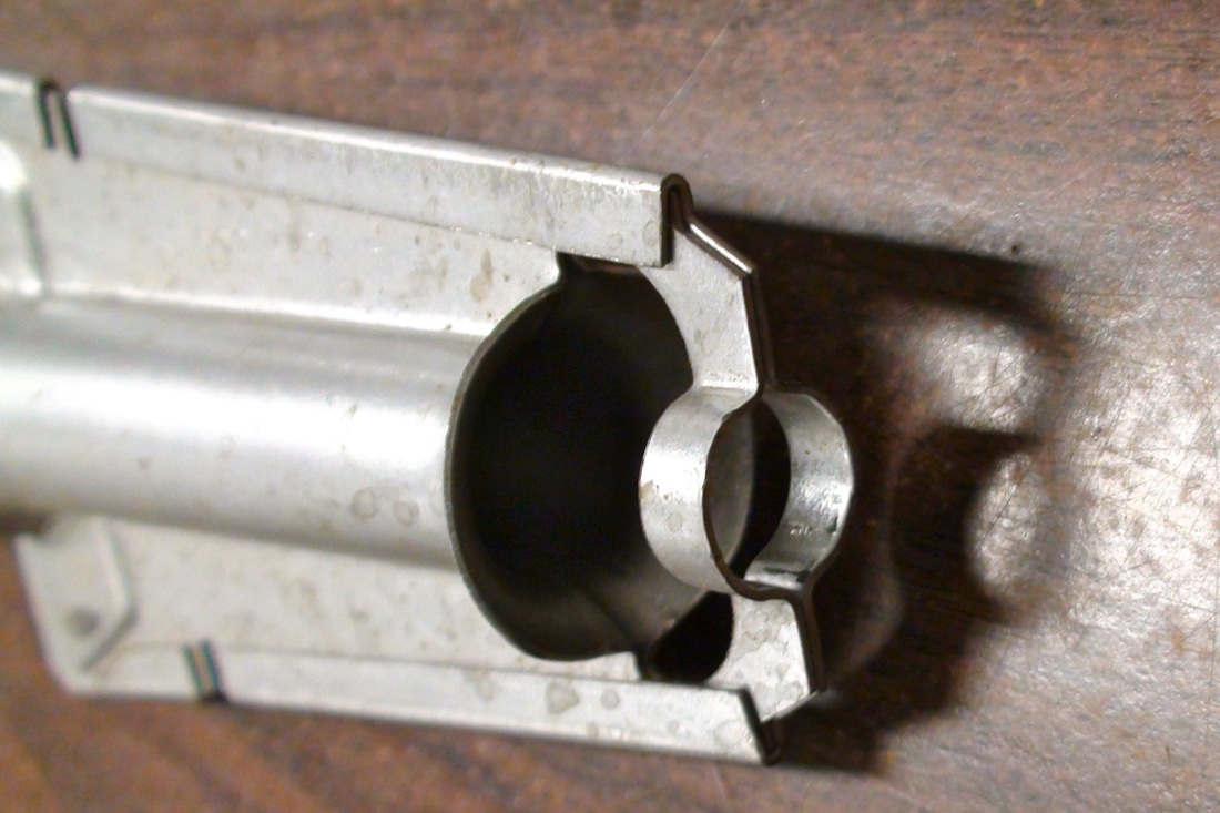
When the pressure is adjusted, the primary air should be adjusted after the setting is done. Many newer furnaces do not have primary air adjustments so when the adjustment of the gas pressure is done the job is finished. The inshot burners below show, on the right, the non adjustable primary air.