Oil Furnace Combustion Analysis
|
|
Combustion analysis
When the burner has been serviced the flame must be set. This means the combustion air needs to be set for the highest efficiency without sooting the appliance.
The best way to do this is with the use of combustion analysis tools.
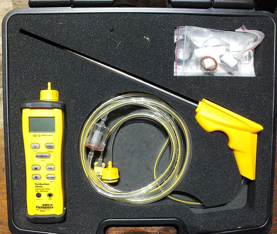
On left is a tool that will sense negative pressure in the smoke pipe, give the stack temperature, give the percentage of CO2 and O2 in the flue gas and calculate efficiency.
A tool similar to this is essential to achieving top performance from the oil burn. When this tool is used, it must be used with the smoke pump (below)
The best way to do this is with the use of combustion analysis tools.
On left is a tool that will sense negative pressure in the smoke pipe, give the stack temperature, give the percentage of CO2 and O2 in the flue gas and calculate efficiency.
A tool similar to this is essential to achieving top performance from the oil burn. When this tool is used, it must be used with the smoke pump (below)
The use of the smoke pump
When the combustion analyzer is used, the smoke pump must also be used.
After the burner has been serviced and is running for at least 10 min, adjust the air shutter to what appears to be a smoky flame as seen through the inspection hole.
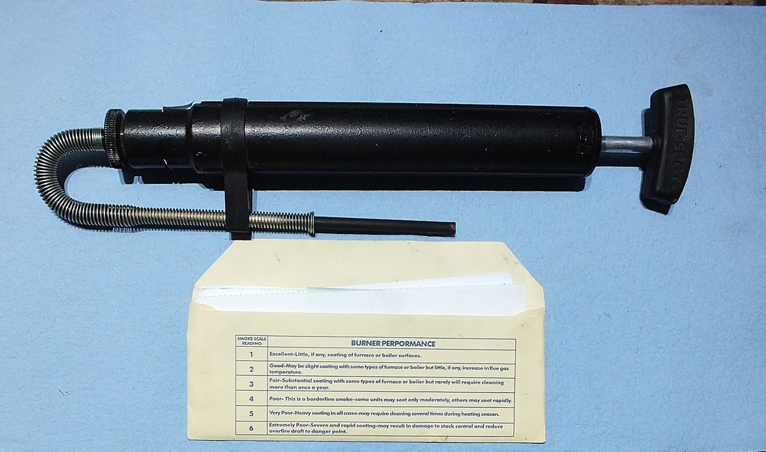
The smoke pump draws a specific amount of exhaust gasses through a patch of white paper with each stroke when the probe is placed into the smoke pipe. The pump is pulled through 10 strokes. The paper is then removed and compared for amount of smoke to the scale that comes with the tool. Your first patch should show some smoke. If it does not, adjust the burner air for less air until you see smoke on the patch. Then adjust the air shutter and retest until the smoke is #0 (this is for flame retention head burners, If the burner is a conventional one, #1 smoke is needed).
After the burner has been serviced and is running for at least 10 min, adjust the air shutter to what appears to be a smoky flame as seen through the inspection hole.
The smoke pump draws a specific amount of exhaust gasses through a patch of white paper with each stroke when the probe is placed into the smoke pipe. The pump is pulled through 10 strokes. The paper is then removed and compared for amount of smoke to the scale that comes with the tool. Your first patch should show some smoke. If it does not, adjust the burner air for less air until you see smoke on the patch. Then adjust the air shutter and retest until the smoke is #0 (this is for flame retention head burners, If the burner is a conventional one, #1 smoke is needed).
The smoke pump is a necessary tool even if you have combustion analysis instruments. You can read high efficiency on the instruments and still have a smoky flame. A smoky flame will cause soot to accumulate on the heat exchanger and insulate it from the air or water passing through.
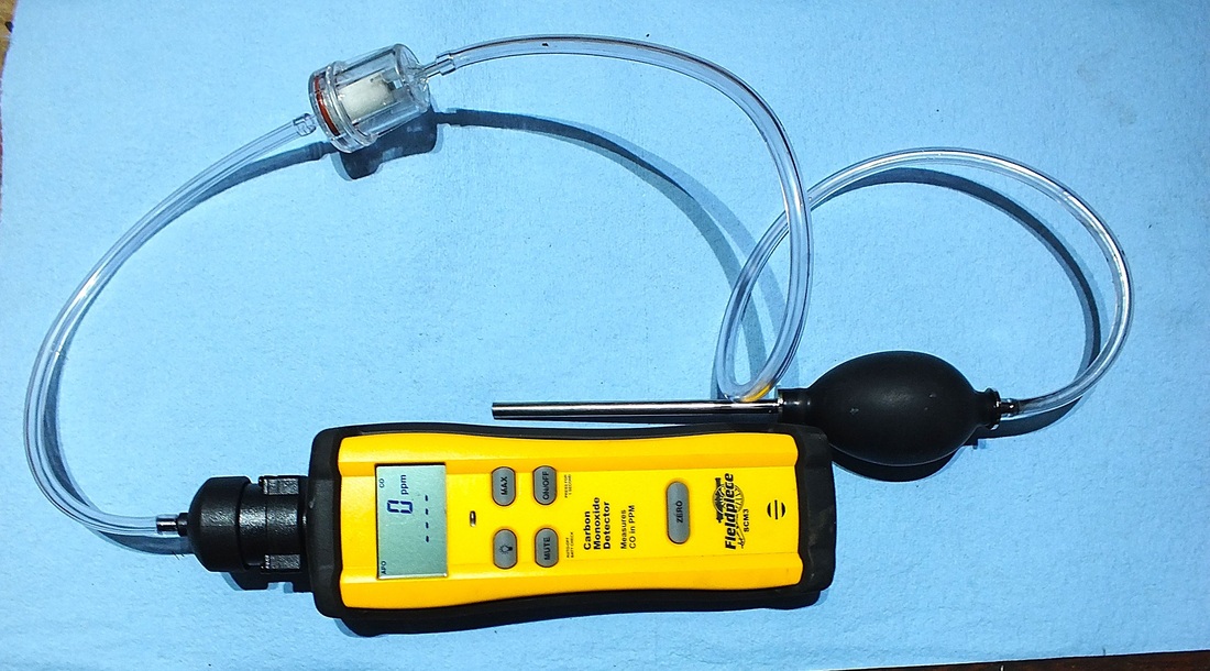
When the proper smoke is achieved, the combustion analyzer is started (it must be calibrated outside the building). The probe is then placed in the smoke pipe and adjustments to the air shutters are made until you achieve the highest efficiency.
Another smoke test is then necessary. If the smoke is proper, lock down the air adjustments and you are finished. If you have a higher smoke than is proper for your burner, you must adjust air until the smoke is good. Do not leave out the last step. The analyzer may read high efficiency and still have excessive smoke. Better to lose some efficiency and not soot up the furnace. 1/8 in of soot is equal to 3 inches of fiberglas insulation, so make sure the fire is clean.
However, any more air than is necessary for good combustion will cool down the flame and cut efficiency by a massive amount. The most common problem problem in setting up oil burners is too much combustion air. If more air than necessary is used it will cool down the flame and the combustion will not be complete. back to annual service
To increase efficiency of an older furnace check here
