- Home
- For the homeowner
- Safety
- Definitions
- Gas furnace
- Some error codes for gas furnaces
- Service sheet for the gas furnace
- gas furnace design
- The gas heat exchanger
- Dangerous conditions in gas furnaces
- Annual service of the gas furnace
- Repair procedures for gas furnaces
- Gas fireplace millivolt systems
- Oil furnace
- Setting gas input
- Quick tips for troubleshooting furnaces
- Troubleshoot
- Operation and troubleshoot furnace by manufacturer
- HVAC war stories blog
- Annual service of an oil furnace
- Oil furnace design
- Oil furnace troubleshoot
- Repair procedures for oil furnaces
- Gas code training
- Piping and connections
- FAG w pilot no fire
- Combustion analysis
- Electric furnace
- Air conditioner
- Refrigeration
- Heat Pump
- Boiler
- Ductwork design and troubleshoot
- Thermostats
- Diagnostic problems
- Tools
- Electric test meters
- Electrical diagram training
- Electrical symbols
- Single and 3 phase power systems
- Electric wiring solutions
- Transformer design and troubleshoot
- Electronic air cleaner
- Blowers and fans design & troubleshoot
- Humidity and humidifiers
- Furnace, Air Conditioner and part manuals
- Electric motors
- Run Capacitors
- Start capacitors
- Troubleshooting the capacitor
- Gas furnace short cycling
How to determine the gas flow to the burners
The gas orifice
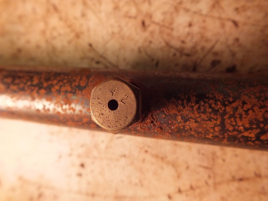
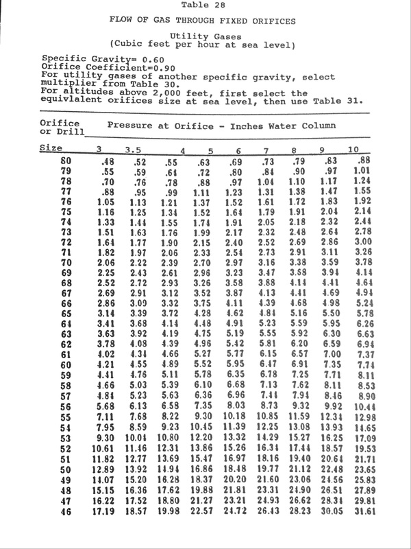
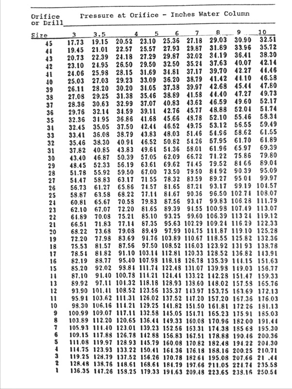
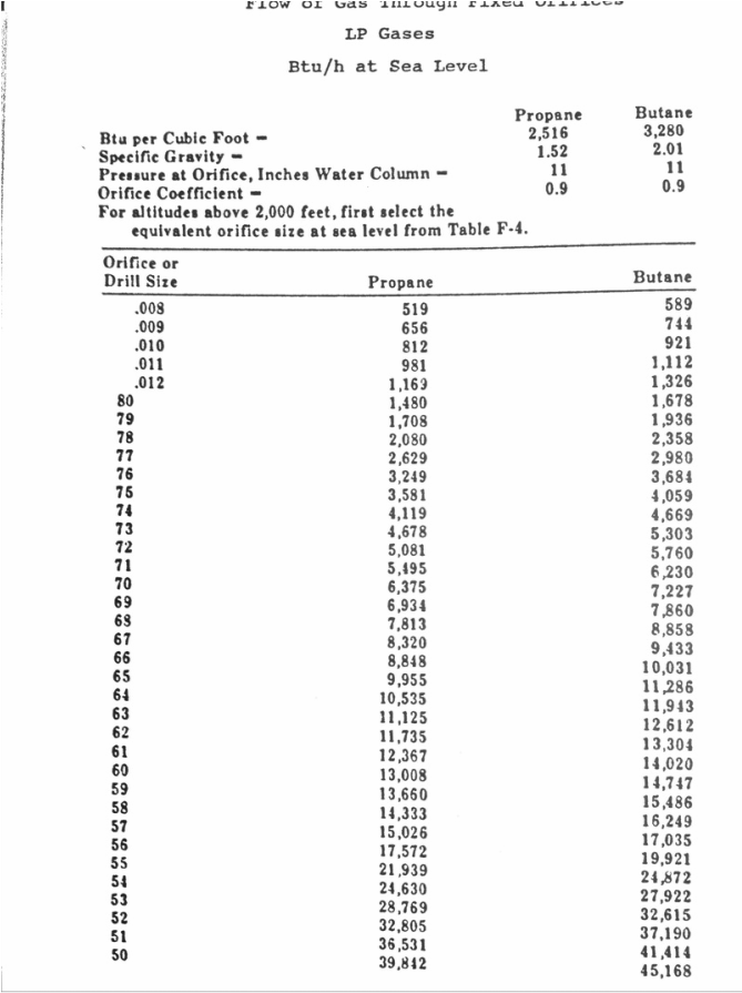
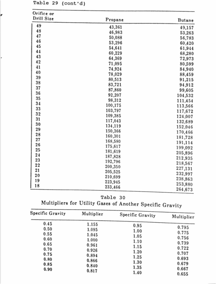
Below are charts that give the amount of gas (the first 2 charts are for natural gas) that will flow through different size orifices at different pressures. The size of the orifice is usually marked on the orifice. If there is no marking, the sizes correspond to the number drills. The orifice to the right is a number 42. Using the chart at 3.5 in wc, this orifice will flow 24,950 BTU.