Combustion analysis
|
|
|
|
The why of combustion analysis
When fuels are burned, the fuel is mixed with air and heat is added to start the combustion of the fuel. At that point, the combustion continues on its own. The combustion process releases the the heat in the fuel.
When burning a gaseous fuel, all that is required is to mix the proper amount of air with the fuel.
Once the fuel is burned, the products of combustion can be measured in the vent gasses.
Combustion analysis determines if the vent gasses have the proper percentages of gasses for efficient combustion.
Gasses we see in vent gasses.
Air is made up of approximately 80% nitrogen. Nitrogen is a stable gas and does not generally take part in combustion and just passes thru.
Oxygen is around 20% of the air. Oxygen is not a fuel but by mixing with the fuel gas at high temperature, the chemical change releases the heat.
Oxygen is around 20% of the air. Oxygen is not a fuel but by mixing with the fuel gas at high temperature, the chemical change releases the heat.
Products of combustion
If the combustion process is complete, the products will be carbon dioxide, water (as a gas) and heat.
If the process is not complete, meaning not enough oxygen, another product will be carbon monoxide. This reduces the combustion efficiency.
If there is too much oxygen mixed with the fuel, the cold air cools off the combustion gasses and reduces efficiency.
If the process is not complete, meaning not enough oxygen, another product will be carbon monoxide. This reduces the combustion efficiency.
If there is too much oxygen mixed with the fuel, the cold air cools off the combustion gasses and reduces efficiency.
Natural gas and propane fuels
|
These gasses have 2 types of combustion air. Primary air and secondary air. The burner on the left has an adjustment for primary air on the left of the burner. Secondary air is air added to the burning gas from around the burner and is not adjustable. The flame is adjusted to just eliminate the yellow tips on the flame. The video below explains combustion of natural gas.
|
Gas furnaces that were designed for natural gas do not generally need vent gas analysis. The only adjustment of the furnace is the primary air, and that only on furnaces older than 1990. All other adjustments are set to factory specs.
The video below shows an analysis of of a gas designed furnace to show the difference in efficiency different primary adjustments can make.
The video below shows an analysis of of a gas designed furnace to show the difference in efficiency different primary adjustments can make.
Fuel oil combustion
Fuel oil is usually #2 diesel. As the oil is liquid, it must be turned into a gas before it can be burned.
The combustion of a liquid is somewhat more complicated and it is easier to have an inefficient burn.
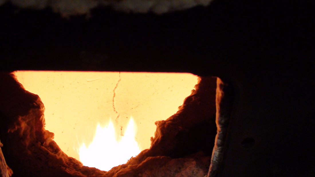
Fuel oil furnaces use high pressure and a nozzle to reduce the oil to very small droplets. Heat is then added by means of a high voltage spark, the heat boils the droplets, air is added and the mixture burns. Combustion takes place in a combustion chamber that holds the heat inside to complete the burn, so efficient combustion does not come about until the combustion chamber warms.
The products of combustion of a complete burn for fuel oil are essentially the same as natural gas with some small amounts of other compounds.
However, all oil furnaces need combustion analysis to get the best efficiency.
The combustion of a liquid is somewhat more complicated and it is easier to have an inefficient burn.
Fuel oil furnaces use high pressure and a nozzle to reduce the oil to very small droplets. Heat is then added by means of a high voltage spark, the heat boils the droplets, air is added and the mixture burns. Combustion takes place in a combustion chamber that holds the heat inside to complete the burn, so efficient combustion does not come about until the combustion chamber warms.
The products of combustion of a complete burn for fuel oil are essentially the same as natural gas with some small amounts of other compounds.
However, all oil furnaces need combustion analysis to get the best efficiency.
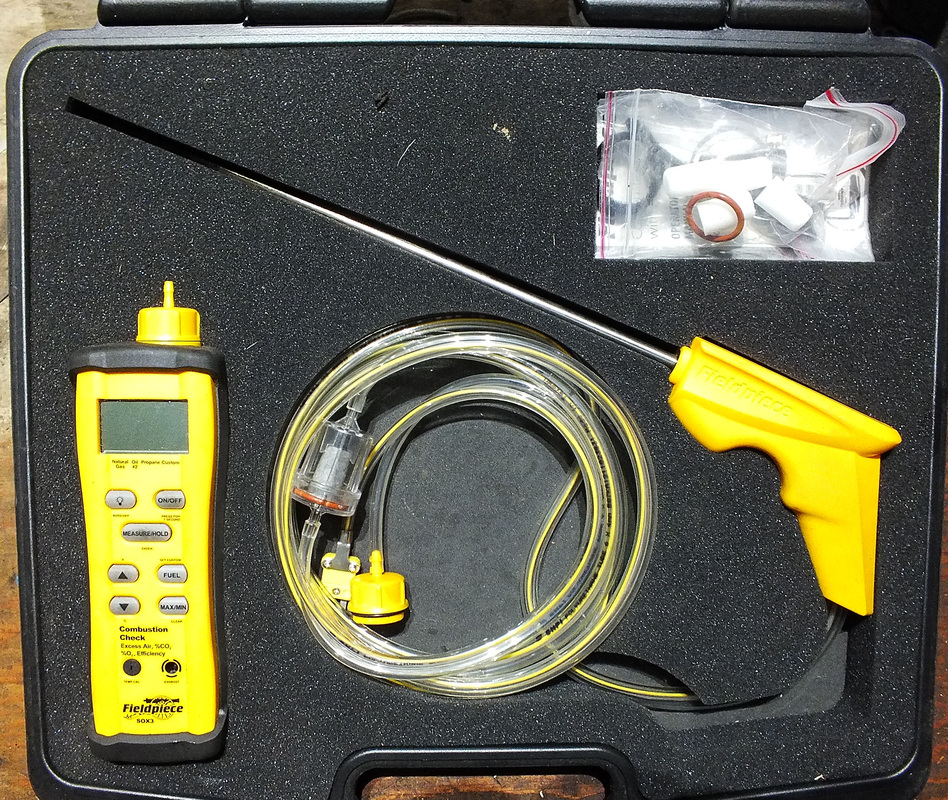
Tools used for combustion analysis for oil furnaces
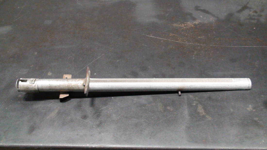
The smoke pump is one of the oldest and most useful of the oil efficiency tools. It consists of a hand operated pump that draws a specific amount of gas from the gasses in the vent pipe. It draws these gasses thru a special paper. The darkening of the paper is compared to a chart to determine how much smoke is in the gasses. It is a simple test that is necessary even if you are using electronic gas analyzers. The video below explains how this tool works.
In order to vent properly there must be a negative pressure in the vent pipe unless the unit is vented by a fan.
We measure the negative pressure with a manometer. This tool measures very small differences in air pressure. In the US we use inches of water column. That is the amount of distance a column of water in a tube will move when subjected to different pressures.
The tool used will measure in 1/100 of an inch water column.
For vent pipes the negative pressure should run about .03 to .04 inches of water column. Any less and the gasses will not rise up the vent dependably and any more and the gasses move too fast thru the heat exchanger to effectively transfer the heat. The video below demonstrates an electronic manometer capable of measuring these pressures.
For how to complete the combustion analysis, check here
