The combination gas valve for gas furnaces
|
|
Gas valve design
The gas valve is not simply a valve. It must have some sort of manual shut off all gas flow, it must provide flame safety to shut down the gas flow during unsafe conditions, it must regulate the gas pressure and it must have an electrically controlled valve to turn on the gas when there is a call for heat. It incorporates at least 4 different components to be able to do its job. Below we will be explaining the different parts and how they work.
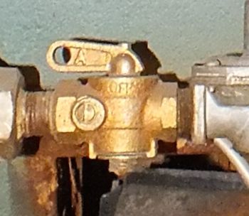
1. Manual valve. This will be a manually operated valve used to turn off all gas supply to the appliance. On older furnaces, it was a separate part in the gas chain.
1. Manual valve. This will be a manually operated valve used to turn off all gas supply to the appliance. On older furnaces, it was a separate part in the gas chain.
|
On the left is a manual gas valve. This one is used in a gas chain. This valve is turned 1/4 turn off or on.
When the handle is lined up with the pipe, it is open. |
|
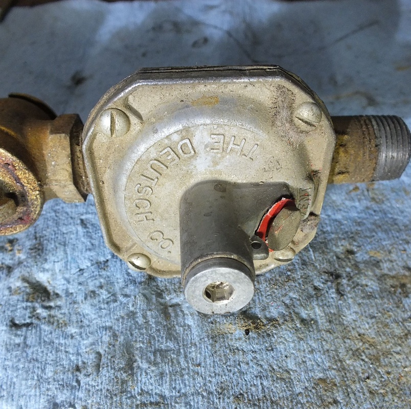
2. Regulator. The regulator on the left is used to reduce the line gas pressure (usually 7" water column for natural gas and 11" water column) to a pressure that can be used in the manifold to distribute the gas to all the burners. The regulator is usually adjustable for field pressure testing. The video below shows how the regulator works.
|
|
3. The solenoid valve
This valve is an electric solenoid that is opened when the thermostat calls for heat. Gas will move through to the burners if all other valves are open. |
|
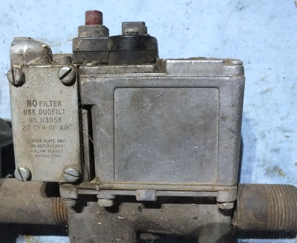
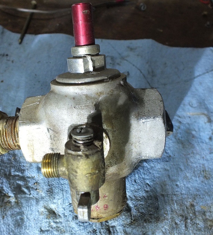
4. The pilot safety
This part is a valve that is held open by an electric voltage produced by a pilot flame. The button on the top(looks like a shaft in the illustration) is pressed to open the valve to allow pilot gas to flow through the manual valve on the front of the safety to the pilot assembly. When the thermocouple is warmed, an electromagnet is energized that holds the main gas valve in the safety open. |

|
The device on the left is a pilot safety that does the same job as the one above. Instead of pushing a button as in the top picture, The red arrow is rotated clockwise.
The video below covers how this pilot safety works. It may give you a better idea of the inside workings of these safeties. |

The pilot safety consists of the pilot burner, thermocouple and the pilot safety solenoid.
The following videos show the operation and testing of the pilot safety.
The following videos show the operation and testing of the pilot safety.

|
Early gas appliances used a chain of the above components to control the burner and provide a flame safety control. The video below explains the gas chain.
|
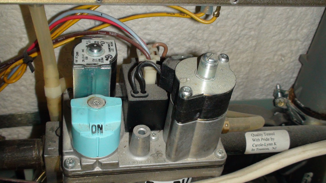
The combination gas valve
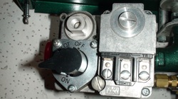
As you can see. the gas chain is rather bulky. It is expensive to make and subject to leaks from the various components. In the early 1960s, the gas chain was replaced by the combination gas valve.
All the functions necessary to the function of a gas burner are incorporated in one package.
The valve above has all the functions of a gas chain.
The black knob is the manual valve.
The regulator is beneath the slot on the top.
The upper left is the screw in terminal for the thermocouple.
The electric terminals on the lower right are for the solenoid valve.
Below is a video of an explanation of the combination gas valve.
The combination gas valve is generally no longer used in most gas appliances. Its job is now being done by electronic ignition controls or IFCs
