- Home
- For the homeowner
- Safety
- Definitions
- Gas furnace
- Some error codes for gas furnaces
- Service sheet for the gas furnace
- gas furnace design
- The gas heat exchanger
- Dangerous conditions in gas furnaces
- Annual service of the gas furnace
- Repair procedures for gas furnaces
- Gas fireplace millivolt systems
- Oil furnace
- Setting gas input
- Quick tips for troubleshooting furnaces
- Troubleshoot
- Operation and troubleshoot furnace by manufacturer
- HVAC war stories blog
- Annual service of an oil furnace
- Oil furnace design
- Oil furnace troubleshoot
- Repair procedures for oil furnaces
- Gas code training
- Piping and connections
- FAG w pilot no fire
- Combustion analysis
- Electric furnace
- Air conditioner
- Refrigeration
- Heat Pump
- Boiler
- Ductwork design and troubleshoot
- Thermostats
- Diagnostic problems
- Tools
- Electric test meters
- Electrical diagram training
- Electrical symbols
- Single and 3 phase power systems
- Electric wiring solutions
- Transformer design and troubleshoot
- Electronic air cleaner
- Blowers and fans design & troubleshoot
- Humidity and humidifiers
- Furnace, Air Conditioner and part manuals
- Electric motors
- Run Capacitors
- Start capacitors
- Troubleshooting the capacitor
- Gas furnace short cycling
90% efficient gas furnaces design and sequencing
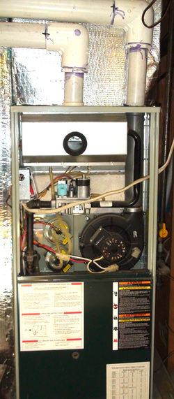
The 90+% furnaces use plastic vent as on this one. These furnaces are getting more common than lower efficiency 80% furnaces.
They vent the burnt gasses with either ABS or PVC vent materials.
Their vent gas temperatures are generally below 120 degrees F.
They are commonly vented out the sidewalls of the structure.
The controls for these furnaces are more complicated than with lower efficiencies.
They are recognized by the plastic venting coming out of the side or the top of the appliance.
This one has the vent on the right side black pipe. The pipe centered on the furnace is combustion air inlet. These appliances can be set up to bring outside air to mix with the gas, thus avoiding removing heated air from the structure. When the unit is set up this way, it is called a sealed combustion appliance.
Note the position of the small black pipe coming out of the gas valve. It travels upward to the burner box. It distributes the gas to small diameter brass orifices which feed the gas to the burners. The burners in this appliance are called inshot burners because they shoot gas into the burners and draw air with the gas to mix air and gas to prepare it to burn. The gas burns, liberating heat which conducts through the heat exchanger wall. A circulating fan is located below the heat exchanger to pass air over the heat exchanger to pick up the heat and distribute it throughout the structure.
Inducer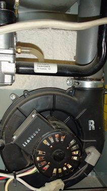
This is an inducer for a 90+% furnace. It pulls gasses out of the heat exchanger to be removed by the plastic pipe. It must prove it is running before a trial for ignition.
|
pressure switches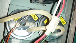
These are the pressure switches that determine if conditions are right for the burners to fire. This is a 2 stage furnace, so there are 2 switches, one for low fire and one for high fire. For an explanation of pressure switches click here |
Burner box
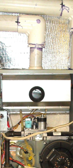
The box directly underneath the plastic pipe is the burner box. Inside the burner box are the burners, the flame rod, the HSI and the holes into which the burners fire. The cover is removable for access to the burners and controls. The window in the center will show a yellow glow from the HSI when there is a trial for ignition. If the burners light, a blue light will be visible. The enclosure for the burners allow the combustion air to be piped from outside the structure so as not to remove air from the structure. In the picture to the left, the center pipe is the combustion air supply.
Because the combustion air supply must have no obstructions, a pressure switch is used to shut down the burners if air is not supplied.
Because the combustion air supply must have no obstructions, a pressure switch is used to shut down the burners if air is not supplied.
The IFC
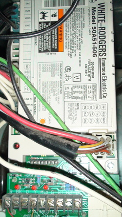
This is the integrated furnace control. This control contains the flame safety control, The time delay for starting and stopping the circulating fan, the operation of the inducer, the connections for the wall thermostat and circuits for the various safeties.
This control would be considered the "brain" of the unit.
On this control, the diagnostic codes are written. Note the small light on the lower left will blink the code. There will be a window in one of the panels that lets you see the code without removing the panel. When the panel is removed, the codes are lost because there is a door switch that opens when the panel is removed killing the power to the unit. Most furnaces will have a key for the codes either on the control or on one of the panels. Some common error codes
Note on this unit, there are 3 small LED lights just above the terminal board. These will also blink a code. They are status lights for the variable speed circulating fan.
Circulating fan
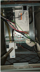
The circulating fan moves the heat through the furnace to the structure and is controlled by the IFC.
The video below shows the cycling of the furnace and gives the results of common failures. It sometimes has advertisements on it so just
click 90% furnace cycling.
The video below shows the cycling of the furnace and gives the results of common failures. It sometimes has advertisements on it so just
click 90% furnace cycling.
90+% gas furnace sequence of operation
1. On a call for heat (thermostat closes), a signal is sent to the IFC and sequencing begins.
2. The IFC electronically looks at the pressure switch.
A. If the pressure switch is open (power cannot pass through), the IFC starts the inducer.
B. If the pressure switch is closed (power passes through), sequencing stops and IFC goes into lockout mode. Lockout code will displayed on the IFC by blinking lights on the module. (key to codes should be listed on the furnace panel).
C. Most IFCs will attempt to try again 10 to 15 minutes later.
3. Once the inducer starts, the pressure switch should close.
A. If the pressure switch does not close, the inducer will continue to run for 1 to 2 minutes then will lockout and try again 10 to 15 minutes later.
B. If the pressure switch closes, the prepurge will begin.
4. The IFC will look at the limit switches.
A. If any of the limit switches are open, the furnace will lockout, the circulating fan will come on and a lockout code will be displayed.
B. If the limit switches are closed, the the warmup time for the HSI begins. A yellow glow will come from one side of the burner box.
5. The HSI warms for from 10 to 45 seconds.
6. The gas valve opens for 4 to 7 seconds to allow gas to pass into the burners. This is called the "trial for ignition"
7. If the burners ignite, the flame is proven, usually by flame rectification, during this time. The flame is sensed by a flame rod on the opposite side of the burners as the yellow glow. There should be a blue light in the burner box.
8. If the burners fail to ignite, the furnace shuts off the gas supply, goes through a purge cycle and attempts to light the burners again.
9. The furnace tries a total of 3 times, then if flame is not established goes into hard lockout. A lockout code will be displayed on the IFC.
10. After 1 hour, the furnace will start the entire sequence again to try to fire off.
11. If the flame is proved, a timer is started to delay the start of the circulating fan for 30 to 40 seconds.
12. When the call for heat is over, the burner extinguishes. The circulating fan continues to run for 2 to 3 minutes to clear heat from the heat exchanger.
13. This sequence is generic. Some furnaces will vary in their actual sequence, but will be substantially the same.
To see some error codes for common furnaces click here


