How to do the combustion analysis of the oil furnace
|
|
The mechanics of combustion analysis
Before starting the burner, be sure the filter is clean and the blower wheel is clean. Once the burner is started, note if there is any rumbling or puffback on startup. These problems must be resolved before attempting combustion analysis. The burner should be operated for about 5 minutes to get the unit up to operating temperature. Look in the inspection hole for soot and a dirty flame.
If all is well, check the negative pressure in the combustion chamber. It should be -.02 in wc. Then check the pressure in the vent pipe. It should be -.04. If there are factory specs, they should be followed.
If the negative pressure in the vent is too low, it indicates a plugged chimney. If the negative pressure in the combustion chamber is too low, the heat exchanger is plugged. If the vent pressure is too high, the barometric damper can be adjusted to add more air and reduce vent pressure. Once the pressures are ok, you can begin the analysis.
|
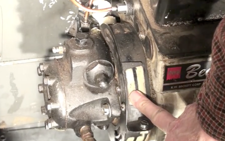
The flame must have the air adjustment set for a slightly smoky flame as a basis for the adjustment. On the left you can see the air adjustment of the Beckett burner.
The smoke pump should be used to check smoke in the vent. It should show a smoke higher than #2. The air adjustment is then moved to achieve a #0 smoke. The video below covers how this is done. |
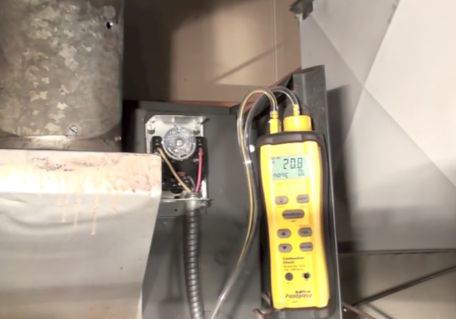
Now we will use a combustion analyzer to determine the percentage of oxygen and CO2 in the vent gasses and the stack temperature. The video below covers the procedures to get the efficiency as good as we can without too much soot in the vent gasses. We are looking for the highest efficiency with a low soot level from the smoke pump. If you use only the analyzer, you may get far too much soot in the vent gasses and the heat exchanger will get soot deposits during the heating season.
You have seen tools used for combustion analysis used in the videos above.
For a look at some of these tools and how they work, check the video below.
For a look at some of these tools and how they work, check the video below.
