Lennox gas furnace design and troubleshoot
|
|
When troubleshooting, understand you are working with potentially lethal voltages and a highly flammable gas. If you do not have the ability to do these operations safely, do not attempt them.
Lennox G16 gas furnace click here
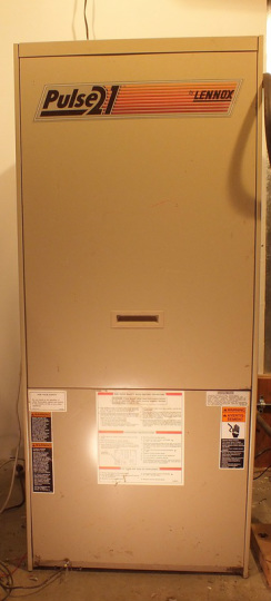
The Lennox pulse G14 and G21 gas furnace
These furnaces were made between 1982 until the middle 1990s.
They used a very different method of combustion.
The combustion is "pulsed" by moving a charge of air and fuel into a combustion chamber to be ignited where the pressure from the expansion of fuel burning moves the charge out of the exhaust and draws a new charge in.
The video below shows theory of operation of this furnace.
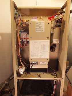
For an overview of all the parts of the pulse, see the video below.
Sequence of operation
The Lennox pulse utilizes a forced draft blower to begin the sequence of operation. The blower operates for 30 seconds to clear the combustion chamber through the air flapper valve. At that point, a spark is initiated in the combustion chamber. The spark operates for 8 seconds to start the combustion. Once combustion is initiated, it is sensed by a flame sensing rod mounted on a spark type plug. After the 8 second trial for ignition, if flame is sensed, the blower and spark stop and combustion continues until flame is no longer sensed or the call for heat is ended. Combustion is characterized by a rumbling noise from the combustion chamber. Below is a video of the sequence of operation.
Below we have a video about the air flapper valve, how it works and and its replacement. The valve allows air into the combustion chamber to mix with fuel when the pressure in the chamber is below atmospheric then closes when the pressure increases during combustion.
For a look at the flapper valve in operation at normal and slow motion check out the video below.
Muffler for the pulse
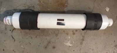
Noise has been a problem for pulse gas furnaces and the company went great lengths to silence the furnace. This includes high amounts of insulation around the flapper chamber, resonator, mufflers (see pic) and expansion tanks. Below is a video demonstration of noise levels around the air flapper valve.
In addition to the air flapper valve, there is a gas flapper valve also. This valve is in the gas line downstream of the gas valve just before the gas orifice. It operates the same as the air flapper but is much smaller. Below is a video explaining the gas flapper valve operation.
Gas manifold pressure is checked on these furnaces in the same way as conventional gas furnaces. The pressure however, is not the same as many gas furnaces. Be sure to read the model plate to find the manifold pressure. Below is a video demonstrating the procedure to test manifold pressure.
The ignition system of this furnace is somewhat different than most furnaces. Because the combustion chamber is under considerable pressure, ignition is accomplished with a spark plug similar to one for automotive use. Flame sense is accomplished by another modified spark plug. The video below explains the plugs.
Troubleshoot of the Lennox pulse furnace
Part 1 of the troubleshoot covers electrical problems from power available to the ignition control. See the video below.
Part 2 of the troubleshoot covers fuel related problems such as flapper valves, or gas valve. See the video below.
Next, we have troubleshoot of the ignition control. This covers spark, flame sense and control board problems. See the video below.
The video below covers a specific failure related to a cracked heat exchanger.
These furnaces had cracks of the heat exchanger that caused poisonous CO gas to be introduced to the structure. A pressure test is necessary to determine for sure that the heat exchanger has cracked.
This is a safety issue and should not be ignored
These furnaces had cracks of the heat exchanger that caused poisonous CO gas to be introduced to the structure. A pressure test is necessary to determine for sure that the heat exchanger has cracked.
This is a safety issue and should not be ignored
