Snyder General gas furnace operation and troubleshoot
|
|
When troubleshooting, understand you are working with potentially lethal voltages and a highly flammable gas. If you do not have the ability to do these operations safely, do not attempt them.
The model GUA060,080,100or125
furnace is covered below.
furnace is covered below.
How the furnace works below
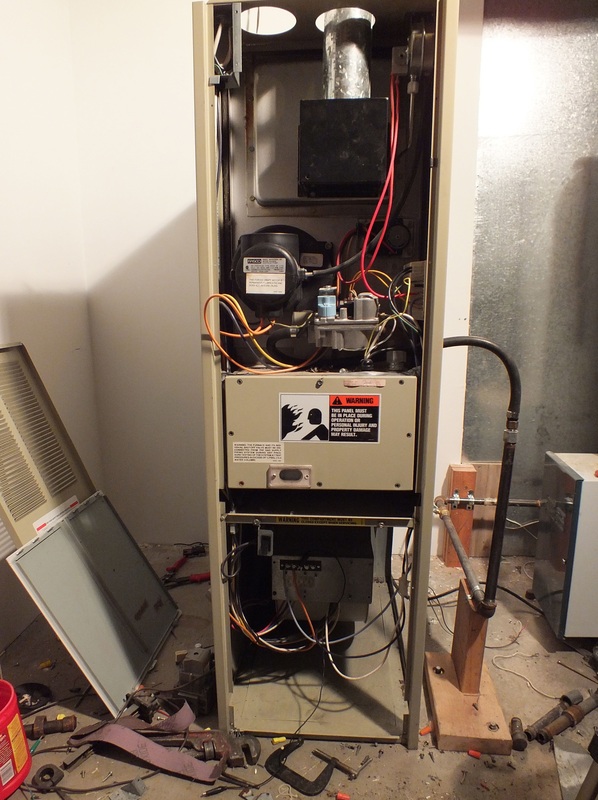
Overview: a look at the furnace
Sequence of operation
On a call for heat, the thermostat energizes the combustion blower.
When the blower reaches top speed, a centrifugal switch on the blower closes.
24 volt power is transferred through the switch, through the normally closed limit switch on the fan and limit switch.
Power then goes to the normally open pressure switch which should be closed when the combustion blower is up to speed.
Power then energizes the ignition control. The ignition control then starts a prepurge timer. This clears out any unburned gasses out of the heat exchanger. When the time expires, the control energizes the HSI. There is a warmup time of 17 seconds for the HSI to glow brightly.
Then the gas valve is opened for a trial for ignition. If the gas lights, the flame rod senses flame, which tells the ignition control flame is present.
The flame stays on and warms the heat exchanger.
The fan and limit switch warms and starts the circulating fan.
Below is a video of how the furnace sequences.
This furnace has a pressurized combustion chamber. The combustion blower blows into the combustion chamber, which requires a shield to keep the blower from putting out the flame. The unit will not operate without the shield. The front cover must also be in place or the flame will roll out the front.
The burners are ribbon type, that is long tubes.
On the right is the HSI, on the left is the flame sensing rod.
The video below shows how the combustion chamber is set up.
The burners are ribbon type, that is long tubes.
On the right is the HSI, on the left is the flame sensing rod.
The video below shows how the combustion chamber is set up.
The forced draft blower
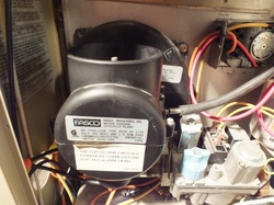
The forced draft blower proves it has started by using a centrifugal switch. This means when the motor reaches full speed, a normally open switch closes to allow 24v power to move from the thermostat "W" toward the pressure switch. The centrifugal switch does not prove that the blower is moving air but only that it is up to speed. There is also no proving that the switch opens when the blower shuts off. The video below shows how it works.
The fan and limit switch
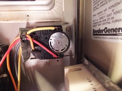
This switch is a combination switch that provides for turning on the fan when the temperature rises in the heat exchanger and shuts it off when the heat exchanger cools.
Also, if the temperature rises above safe levels, it will shut off the burners.
On this furnace, the power from the centrifugal then goes through the normally closed limit switch.
The video below gives a demonstration of how to set the temperature set points on the fan and limit switch.
Also, if the temperature rises above safe levels, it will shut off the burners.
On this furnace, the power from the centrifugal then goes through the normally closed limit switch.
The video below gives a demonstration of how to set the temperature set points on the fan and limit switch.
The pressure switch
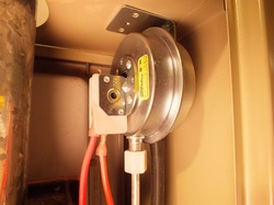
The pressure switch is mounted on the upper right of the furnace. It has taps off of both sides of the diaphragm. The switch on the diaphragm is normally closed. One side taps the combustion air inlet to check for high negative pressure indicating a blocked combustion air inlet. The other tap checks for excessively high pressure in the vent indicating a blockage in the vent pipe. As with the centrifugal switch, it does not have prove its operation before the burners starts. The video below covers pressure switch operation.
The ignition control
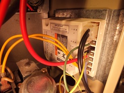
The 24v power then goes to the ignition control. This control is responsible for flame safety control. It also provides prepurge, switching of the HSI and flame sensing features. The video below tells how it works.
Setting manifold pressure
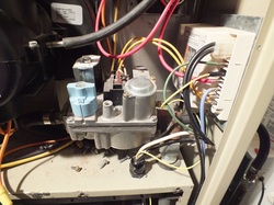
The gas valve is shown on the left. When servicing or replacing the gas valve, the manifold pressure must be set. For a complete discussion of setting gas input click here For gas input charts click here.
For a method of determining gas flow by clocking the meter, cut and paste the following address: http://youtu.be/I0bWSBVCXbo
For a method of determining gas flow by clocking the meter, cut and paste the following address: http://youtu.be/I0bWSBVCXbo
