The hot water boiler circulating system
|
|
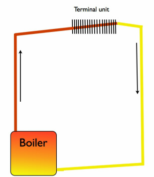
The above diagram is a simplified boiler gravity circulating system.
As the water arrives at the bottom of the boiler, the burning fuel warms the water. The warm water naturally rises through the angled pipes to the terminal unit which transfers the heat from the water to the heated space. As the water cools, it travels back to the bottom of the boiler to be reheated. The wall thermostat simply turned on the burner. This type of system is characterized by large diameter piping and angled piping as show in the diagram. This type of system was common in the early part of the 20th century.
These systems had the advantage that no electrical power was needed for them to work.
The disadvantage was that using heat to move the water is very inefficient.
|
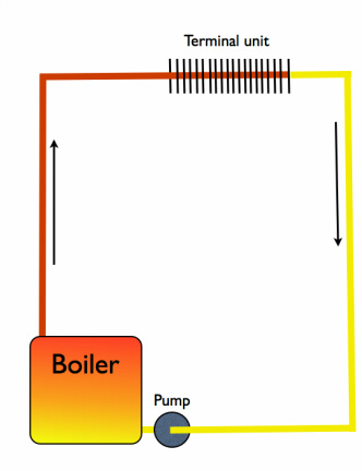
This system adds a circulating pump to the boiler.
The pump added a number of improvements to the system. Water movement was now controlled by the pump. This a much more efficient way to move water. The pipe size is smaller and there is no need for the pipes to be graded to assist flow. Also, when the system operates by gravity flow, the boiler tended to overheat the structure due to the inertia of the large amounts of water traveling through the pipes. When the pump shuts down, it, at least somewhat inhibits the flow of water. |

|
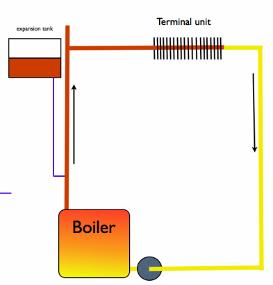
On the left we have added more components.
When water warms, it takes up more space. We add an expansion tank located at a higher level than the highest part of the system. When the water heats, the level in the expansion tank rises. As it cools, the level drops. There is a float valve to allow domestic water to come into the tank as it evaporates. These expansion tanks were used up until about 1935. Later the type shown below was common. |
|
This a different type of expansion tank. It does not have an open top. The tank is filled with air, then water is charged into the system at about 12#. The air is pressurized and the level rises to about 1/2 full. When the water warms, it rises against the air trapped above it. |
The expansion tank
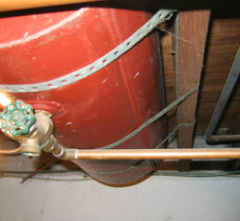
This is what an expansion tank may look like. It is usually mounted in the rafters above the boiler. It needs to above the boiler but may be below the radiators. The video below explains the operation of the expansion tank.
In modern boilers systems, the expansion tank has been eliminated in favor of the bladder tank. This tank is separated into 2 compartments. One side has water from the boiler and the other has a precharged pressure usually equal to the boiler pressure. Nominally 12#. There is a rubber diaphragm between the 2. The rubber will stretch as the volume increases due to temperature rise. This eliminates the periodic recharging of air into the expansion tank.
All but larger commercial systems now use the bladder tank.
All but larger commercial systems now use the bladder tank.
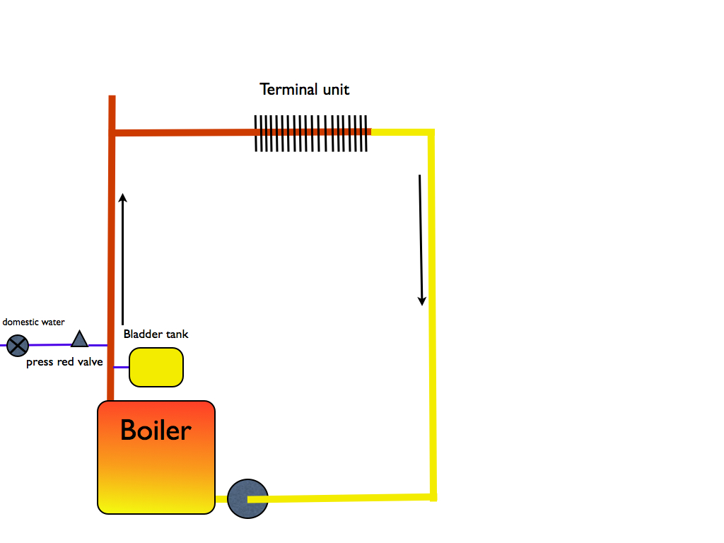
Pressure reducing valves
Boilers are charged with domestic water upon startup. However, boiler pressure must be maintained at a lower pressure than domestic. To do this we use a pressure reducing valve. This is an adjustable valve placed between the water supply and the boiler. The valve is shown above on the left. A video on the design of this valve is shown below.
