What is water column pressure and manifold pressure as used in gas appliances
Water column pressure
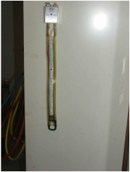
On the left is a slack tube manometer or water column gauge. When pressure is applied to one of the fittings on top, the water lowers in one column and raises in the other. The water column pressure is the total of the 2 readings.
To give an idea of the pressure involved, 28 inches of water column is equal to 1# of pressure.
Below is a video of the different types and uses of water column gauges.
To give an idea of the pressure involved, 28 inches of water column is equal to 1# of pressure.
Below is a video of the different types and uses of water column gauges.
Line pressure.
Natural gas is transported across country in high pressure pipes. Around 900 psi. Once it reaches the gas supplier, the pressure is dropped to various pressures determined by the gas supplier to meters located outside buildings. At this point, the pressure is regulated down to 5 psi for very large consumers, 2 psi for somewhat smaller consumers, however, most consumers use 7 inches of water column from the meter to the appliance.
Gas pressures upstream of the meters is something that gas furnace technicians are not concerned with. The utilities are federally regulated for their supply systems.
Bypassing the meter can and will bring catastrophic pressures into the gas system. Gas valves are rated at 1/2 psi and if higher pressures are encountered almost certainly diaphragm rupture will occur with a resulting fire or explosion.
The 7 inch water column pressure (1/4 psi) is received by the gas valve and reduced by its regulator to a lower pressure that the manifold distributes to the gas orifices.
Below is a video explaining gas regulator operation.
Manifold pressure
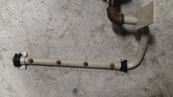
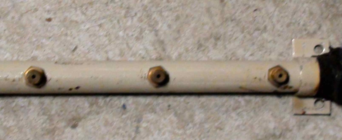
On the left is a gas manifold. It transports the gas from the gas valve to the orifices that supply the burners
|
The orifices are precisely drilled holes mounted on the manifold.
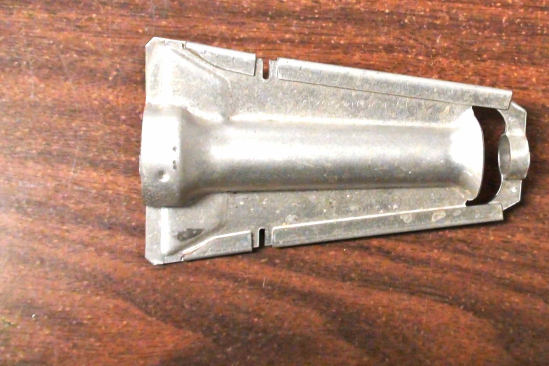
The orifices fit on to the burners and spray the gas into the burner tube. When the gas enters the burner, it draws primary air in with it to prepare the gas to burn. The mix of gas and air ignites when it leaves the burner and finishes the burn with secondary air from around the burner. On the left is a an inshot burner used on most newer furnaces. The gas goes in on the right and the flame goes out on the left. Below is a ribbon burner. These were used on older furnaces. The gas goes in on the left and comes out the top. 
|
The 2 things that determine the amount of gas burned are the manifold pressure and the size of the orifice.
The manifold pressure can be adjusted by turning the regulator clockwise to increase pressure and counter clockwise to decrease.
All furnaces built in the last 25 years must be set to factory specifications for the amount of gas burned.
If too much gas is supplied, the heat exchanger will be burnt out. If too little, condensation of the burnt gas will occur and rust out the heat exchanger.
