Controls for medium (80%) efficiency gas furnaces
Integrated furnace control
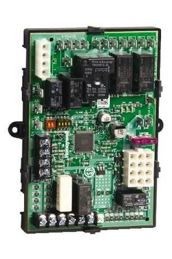
Most modern furnaces use electronics to control all cycling of their furnaces as seen on the left.
There may be a small window on the furnace cover through which you can see any error codes that have occurred.
A key to the codes is usually on the inside of one of the covers. Some error common codes
This code does not necessarily tell you what is wrong, but tells you what part of the furnace to look for the problem.
Most modern furnaces use this control system with some variations to control their appliances.
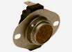
The above images are of limit switches that are placed into the airflow to sense if the air coming out of the furnace is excessively high. If it exceeds a preset temperature, it will signal the Integrated furnace control and the control will shut down the burners and turn on the circulating fan. It will also blink an error code on the IFC.
Rollout switch
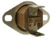
This limit switch is used to stop the burners when unsafe conditions require someone to physically reset the switch. The rectangular button in the center of the switch pops out when overheated and the switch will not automatically reset. Turning off the power and rebooting the furnace will not reset this switch.
These switches are commonly used as rollout switches. This switch is usually wired in series with all other limit switches. If this switch is open, it should not be reset until the cause for the failure is determined. It should NOT be bypassed.
These switches are commonly used as rollout switches. This switch is usually wired in series with all other limit switches. If this switch is open, it should not be reset until the cause for the failure is determined. It should NOT be bypassed.
High temperature fuse
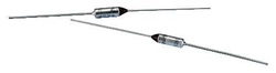
These controls are sometimes used as rollout switches. They cannot be reset and must be replaced. As with rollouts, these should not be replaced until the cause for the failure is determined.
These should NOT be bypassed.
For a complete sequence of operation of these furnaces, see below:
Back
These should NOT be bypassed.
For a complete sequence of operation of these furnaces, see below:
Back
80% gas furnace sequence of operation
1. On a call for heat (thermostat closes), a signal is sent to the IFC and sequencing begins.
2. The IFC electronically looks at the pressure switch.
A. If the pressure switch is open (power cannot pass through), the IFC starts the inducer.
B. If the pressure switch is closed (power passes through), sequencing stops and IFC goes into lockout mode. Lockout code will displayed on the IFC by blinking lights on the module. (key to codes should be listed on the furnace panel).
C. Most IFCs will attempt to try again 10 to 15 minutes later.
3. Once the inducer starts, the pressure switch should close.
A. If the pressure switch does not close, the inducer will continue to run for 1 to 2 minutes then will lockout and try again 10 to 15 minutes later.
B. If the pressure switch closes, the prepurge will begin.
4. The IFC will look at the limit switches.
A. If any of the limit switches are open, the furnace will lockout, the circulating fan will come on and a lockout code will be displayed.
B. If the limit switches are closed, the the warmup time for the HSI begins. A yellow glow will come from one side of the burner box.
5. The HSI warms for from 10 to 45 seconds.
6. The gas valve opens for 4 to 7 seconds to allow gas to pass into the burners. This is called the "trial for ignition"
7. If the burners ignite, the flame is proven, usually by flame rectification, during this time. The flame is sensed by a flame rod on the opposite side of the burners as the yellow glow. There should be a blue light in the burner box.
8. If the burners fail to ignite, the furnace shuts off the gas supply, goes through a purge cycle and attempts to light the burners again.
9. The furnace tries a total of 3 times, then if flame is not established goes into hard lockout. A lockout code will be displayed on the IFC.
10. After 1 hour, the furnace will start the entire sequence again to try to fire off.
11. If the flame is proved, a timer is started to delay the start of the circulating fan for 30 to 40 seconds.
12. When the call for heat is over, the burner extinguishes. The circulating fan continues to run for 2 to 3 minutes to clear heat from the heat exchanger.
13. This sequence is generic. Some furnaces will vary in their actual sequence, but will be substantially the same.
To see some error codes for common furnaces click here
