- Home
- For the homeowner
- Safety
- Definitions
- Gas furnace
- Some error codes for gas furnaces
- Service sheet for the gas furnace
- gas furnace design
- The gas heat exchanger
- Dangerous conditions in gas furnaces
- Annual service of the gas furnace
- Repair procedures for gas furnaces
- Gas fireplace millivolt systems
- Oil furnace
- Setting gas input
- Quick tips for troubleshooting furnaces
- Troubleshoot
- Operation and troubleshoot furnace by manufacturer
- HVAC war stories blog
- Annual service of an oil furnace
- Oil furnace design
- Oil furnace troubleshoot
- Repair procedures for oil furnaces
- Gas code training
- Piping and connections
- FAG w pilot no fire
- Combustion analysis
- Electric furnace
- Air conditioner
- Refrigeration
- Heat Pump
- Boiler
- Ductwork design and troubleshoot
- Thermostats
- Diagnostic problems
- Tools
- Electric test meters
- Electrical diagram training
- Electrical symbols
- Single and 3 phase power systems
- Electric wiring solutions
- Transformer design and troubleshoot
- Electronic air cleaner
- Blowers and fans design & troubleshoot
- Humidity and humidifiers
- Furnace, Air Conditioner and part manuals
- Electric motors
- Run Capacitors
- Start capacitors
- Troubleshooting the capacitor
- Gas furnace short cycling
"80% efficient" gas furnace design and sequencing
If the appliance has a galvanized pipe coming out of the top of the appliance it is considered 80% efficient if it was built within the last 25 years.
These appliances still use the heat from the exhaust gasses to remove them from the structure.
They use inducers to help remove the burnt gasses.
Most of the controls for these furnaces are similar to 90% efficient appliances.
These appliances still use the heat from the exhaust gasses to remove them from the structure.
They use inducers to help remove the burnt gasses.
Most of the controls for these furnaces are similar to 90% efficient appliances.
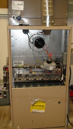
Parts of an 80% efficient furnace

The vent gasses leave the appliance through the silver pipe at the top of the appliance.
The inducer is located below the vent pipe.
A pressure switch is located to the left and above the inducer.
Gas supply comes in from the left and ends at the gas valve.
The black pipe on the right of the gas valve is called the manifold. It distributes the gas to small diameter brass orifices which feed the gas to the burners. The burners in this appliance are called inshot burners because they shoot gas into the burners and draw air with the gas to mix air and gas to prepare it to burn.
The gas burns, liberating heat which conducts through the heat exchanger wall. A circulating fan is located below the heat exchanger to pass air over the heat exchanger to pick up the heat and distribute it throughout the structure. Next
